Apstra Demonstration Lab
About This Guide
Introduction
Welcome to the Juniper Apstra Demonstration Lab Guide. This comprehensive resource has been designed specifically for Sales Engineers and Partner Sales Engineers to effectively demonstrate the powerful capabilities of Juniper’s Intent-Based Networking platform. Rather than simply presenting individual features, this guide provides a cohesive narrative that showcases how Apstra delivers tangible business value throughout the entire network lifecycle.
Purpose and Scope
This guide covers the complete Apstra demonstration workflow, from fundamental concepts through to advanced operational scenarios. Each section builds upon the previous one, creating a logical progression that mirrors real-world network management challenges and their solutions. The demonstrations are structured to highlight not only how Apstra works but, more importantly, why its capabilities matter to organisations seeking to transform their data centre operations.
This guide is based on Apstra version 6.0.0, though the core concepts and demonstration workflows can generally be applied across different versions with minor adjustments. Prior understanding of Apstra fundamentals is beneficial but not strictly required to follow this guide.
Value Point: By following this structured approach, you can demonstrate how Apstra reduces operational complexity while simultaneously increasing reliability and agility—addressing the core challenges faced by enterprise network teams today.
How to Use This Guide
Each section of this guide is designed to be both standalone and part of a cohesive whole. This modular approach allows you to:
Present a complete end-to-end demonstration (though not necessarily in a single session)
Focus on specific capabilities that address particular customer pain points
Build customised demonstrations that align with specific customer requirements
Navigate between related features to respond to spontaneous questions
This guide is intended to be a comprehensive reference that you can draw from as needed, rather than a script that must be followed from beginning to end in a single session. You can select the most relevant sections based on your customer’s interests and time constraints.
Customer Question: “Which parts of your network operations consume the most time and resources today?”
Storytelling Tip: Begin demonstrations by establishing the customer’s current operational challenges. This creates context for how Apstra’s automation and assurance capabilities deliver specific value to their environment.
Access Details
Once you have submitted the form check your inbox and you should have received an email from (_jcl-hol@juniper.net) containing the lab details as show below.
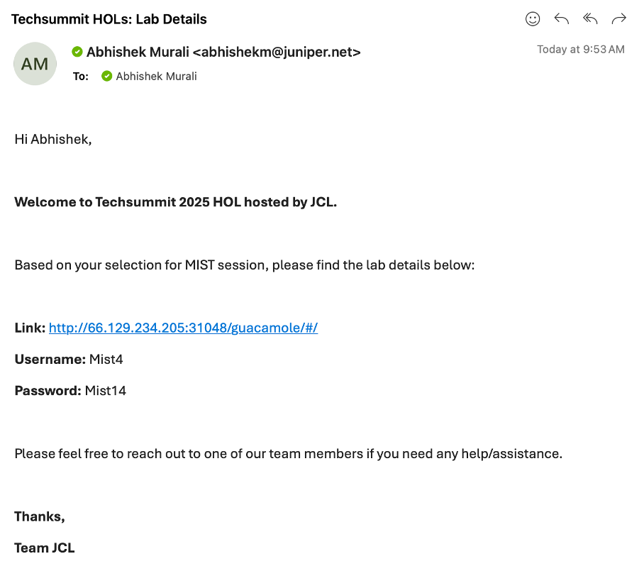
Open a browser and http into server Link provided to you in the above email.
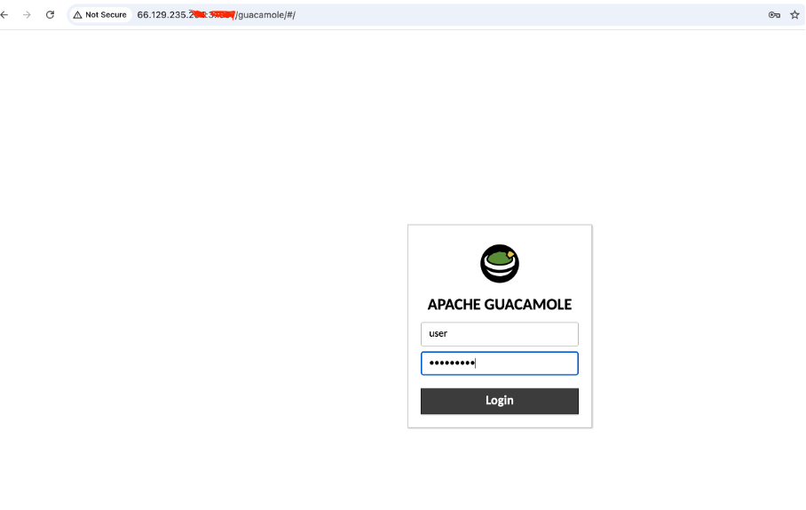
Login with username and the password shared via email.
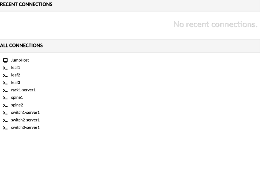
Click on JumpHost, to login:
user - jumpstation
password - Juniper!1
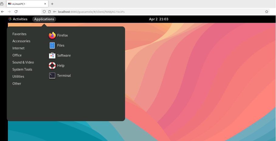
Open a Firefox browser and navigate to Apstra UI: https://100.123.0.74 with username: admin and password: Juniper!1
Navigate to Blueprints, You will be working with 00x_user_demo_bp blueprint.
x - corresponds to the username you received over email
Creating Effective Customer Demonstrations
It’s important to understand that the purpose of this lab guide is not simply to show you what to demo, but rather to teach you how to effectively demonstrate Apstra to customers. There is a crucial distinction here:
This guide is a teaching tool, not a rigid demonstration script.
Each customer will have different priorities, challenges, and interests. The most effective demonstrations are those that directly address these specific needs rather than following a one-size-fits-all approach. This lab shows you one way of structuring an Apstra demonstration and provides a foundation from which you can develop your own customised story.
Value Point: The ability to tailor Apstra demonstrations to specific customer environments and challenges dramatically increases their impact and relevance.
Customer Questionion: “How would this specifically address our organisation’s unique network architecture and operational processes?”
Storytelling Tip: Use this guide as a starting point, then incorporate your own experiences and customer knowledge to create demonstrations that feel personally relevant to each customer. Share real examples from your experience where similar customers have benefited from specific Apstra capabilities.
We encourage you to:
Understand your customer first: Before planning any demonstration, have discovery conversations to identify their specific pain points and priorities
Select relevant sections: Choose the parts of this guide that directly address those specific needs
Adapt the storytelling: Modify the examples and narratives to reflect the customer’s industry and environment
Develop your own style: Incorporate your personal experiences and knowledge to make the demonstrations authentic and credible
Be responsive: Be prepared to pivot during demonstrations based on customer reactions and questions
Remember that the most compelling demonstrations are those that show customers how Apstra solves their specific problems, not just how the technology works in isolation.
The Network Operations Lifecycle: Understanding the Operations Donut
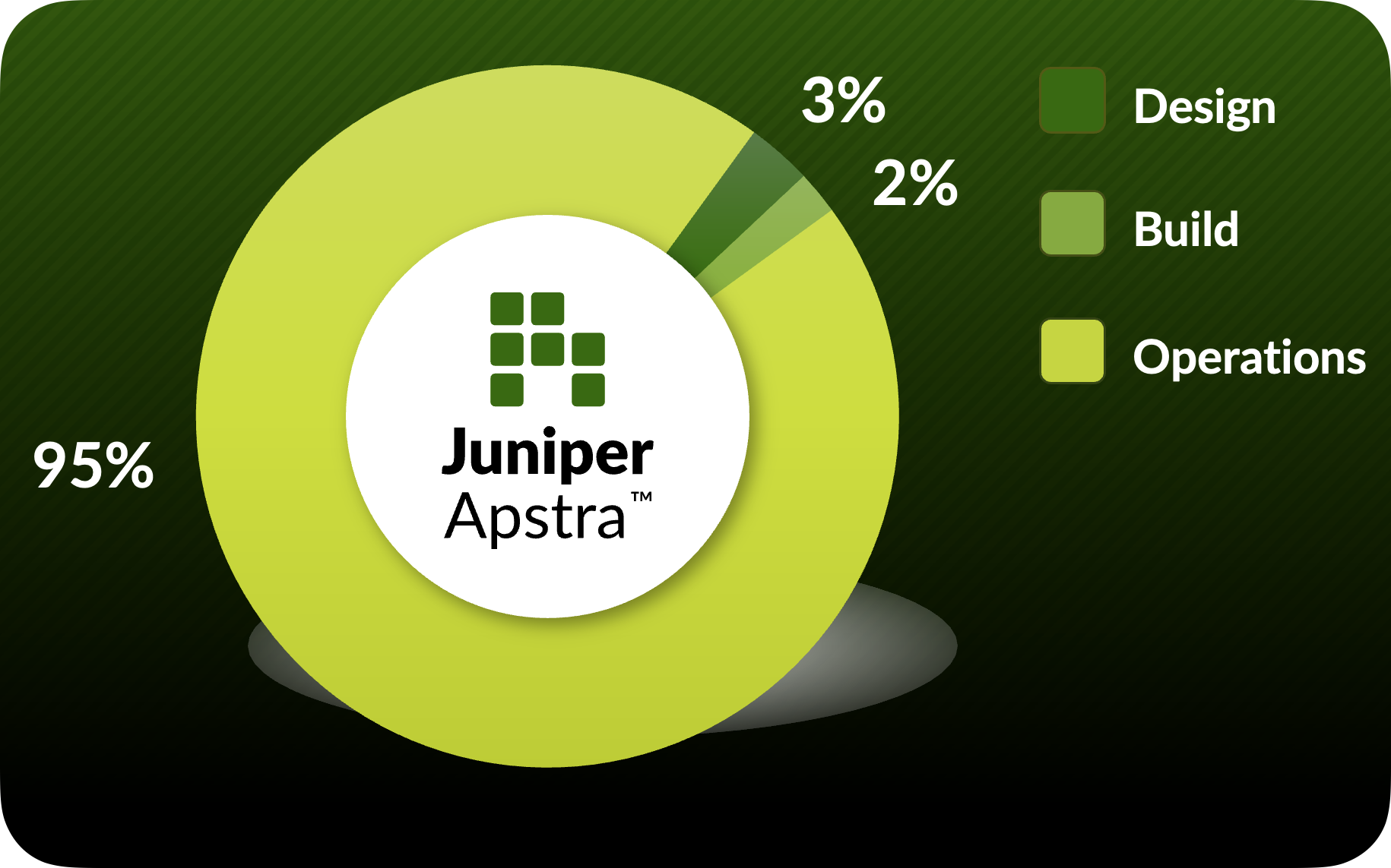
At the core of Apstra’s value proposition is its ability to address the entire network operations lifecycle—visualised as the “Operations Donut.” This comprehensive approach ensures that networks are not only deployed correctly but continue to operate reliably while adapting to changing business requirements.
A Critical Perspective: The Reality of Network Operations
What the Operations Donut reveals is a fundamental truth about data centre networks: the vast majority of a network’s lifecycle is spent in operations, not design or deployment. As illustrated in the diagram, approximately:
3% of time is spent in Design
2% of time is spent in Build
95% of time is spent in Operations (Day 2)
This operational reality includes critical activities such as:
Adding racks (Day 200)
Responding to power outages (Day 395)
Troubleshooting packet drops (Day 480)
Adding virtual networks (Day 741)
Changing vendors (Day 1400)
Value Point: While many networking solutions focus primarily on initial deployment, Apstra uniquely addresses the complete lifecycle with particular emphasis on the operational phase—where organisations spend most of their time, resources, and face their greatest challenges.
Customer Question: “What proportion of your networking team’s effort is spent on ongoing operations versus new deployments?”
Storytelling Tip: The Operations Donut provides a powerful visual representation of why traditional networking approaches fall short. Most tools focus on the small slices of design and build, leaving teams to manage the massive operational portion with fragmented, manual processes.
Traditional Day 0/1/2 Approach vs. Apstra’s Unified Lifecycle
In traditional networking terminology:
Day 0: Network design and planning phase (3% of lifecycle)
Day 1: Initial implementation and deployment (2% of lifecycle)
Day 2: Ongoing operations, maintenance, and changes (95% of lifecycle)
While many solutions address only portions of this lifecycle, Apstra provides comprehensive capabilities across all phases through a single platform with a unified data model—with particular strength in the critical Day 2 operations that dominate the network’s life.
Value Point: Apstra transforms Day 2 operations from a fragmented, reactive process into a structured, intent-driven approach that maintains the same level of validation and automation traditionally reserved only for initial deployment.
The Operations Donut encompasses key Apstra capabilities:
Design & Build: Creating intent-based templates and blueprints
Deploy: Implementing configurations across multi-vendor environments
Validate: Ensuring deployed networks match intended designs
Operate: Day-to-day management and troubleshooting
Optimise: Continuous improvement through analytics and automation
Customer Question: “How much time does your team currently spend validating that network changes have been implemented correctly?”
Storytelling Tip: Share how customers have reduced their change implementation times by 80% whilst simultaneously reducing post-change incidents through Apstra’s closed-loop validation. Emphasize that Apstra’s true value is in supporting network engineers and business operations during the extensive Day 2 phase where traditional approaches fall short.
Lab Environment Overview
The demonstrations in this guide are designed to run on a combination of environments:
A lab environment that you can configure according to your specific demonstration needs
Pre-configured Apstra environment for demonstrating Apstra-Flow and Apstra Cloud Services (All Read Only)
Apstra server running version 6.0.0
Simulated data centre fabric (spine-leaf architecture)
Pre-configured virtual networks and endpoints
This flexible approach allows for realistic demonstrations of Apstra’s capabilities without requiring extensive physical hardware. The guide includes specific instructions for accessing and utilising both custom lab environments and the pre-configured Apstra Cloud Labs where applicable.
Value Point: Apstra’s ability to manage multi-vendor environments from a single platform eliminates the need for multiple management tools and specialised training for each vendor’s CLI—significantly reducing operational complexity and costs.
Guide Structure
This guide is organised into four main sections:
Apstra Fundamentals: Core concepts, architecture, and UI familiarisation
Day 2 Change Delivery: Practical scenarios for network expansion and modification
Day 2 Operations & Assurance: Monitoring, troubleshooting, and optimisation
Demo Tools and Resources: Additional capabilities and environment management
Each section builds upon the previous one, creating a logical flow that demonstrates how Apstra addresses the complete network lifecycle.
Customer Question: “What aspects of network operations create the most risk in your environment today?”
Storytelling Tip: Use the guide’s structure to illustrate how Apstra creates a ‘virtuous cycle’ of improved reliability through automation, validation, and continuous assurance.
Understanding Apstra Architecture & Intent-Based Networking
Foundation of the Pre-Built Fabric
Business Context
Traditional network management approaches treat infrastructure as isolated components, leading to fragmented operations, configuration inconsistencies, and lengthy troubleshooting cycles. Apstra fundamentally changes this paradigm through Intent-Based Networking (IBN), where the network is managed as a unified system based on business outcomes rather than device-by-device configurations. This architectural approach creates a resilient, predictable network environment that continuously validates itself against defined intents.
Objectives
Understand Apstra’s architectural principles and how they differ from traditional approaches
Explore the concept of Intent-Based Networking and its business implications
Examine how Apstra’s reference designs enforce best practices while allowing customisation
Introduce the pre-built fabric as a practical demonstration of these principles in action
Overview
This module serves as the foundation for our entire demonstration guide. We begin with theoretical understanding of Apstra’s architecture and Intent-Based Networking principles before exploring a pre-built fabric. This approach helps customers grasp the fundamental paradigm shift that Apstra represents before seeing it in action.
Architectural Foundations
1. The Apstra Architectural Advantage
Apstra’s architecture is built around a fundamental principle: understanding context. Unlike traditional tools that merely collect data, Apstra maintains a comprehensive understanding of:
Network topology and physical relationships
Service dependencies and abstraction layers
Expected behaviours and states across all elements
Protocol-specific characteristics and requirements
Value Point: This context-aware approach enables Apstra to not just monitor the network but to truly understand it, interpreting data within its proper framework rather than as isolated metrics.
Customer Question: “How much effort does your team spend trying to correlate information from different systems to understand your network’s actual state?”
Storytelling Tip: Compare traditional network management to having hundreds of security cameras but no guards watching them—data is collected but not interpreted. Apstra not only watches all cameras but understands what normal patterns look like and alerts on meaningful deviations.
2. Intent-Based Networking Principles
At its core, Intent-Based Networking (IBN) revolves around four key capabilities:
Translation: Converting business requirements into network configurations
Activation: Implementing these configurations across the infrastructure
Assurance: Continuously validating that the network behaves as intended
Optimization: Learning from operational patterns to suggest improvements
Value Point: This approach fundamentally shifts networking from a configuration-focused discipline to an outcome-focused one, aligning network operations with business objectives.
Customer Question: “How do you currently ensure that your network configurations actually deliver the business outcomes they were intended to support?”
Storytelling Tip: Explain how IBN is similar to modern automotive systems—you specify the destination (intent), and the vehicle’s systems handle the acceleration, braking, and navigation details (implementation) while continuously checking that you’re on the right path (validation).
3. Reference Design Methodology
Apstra guides users through pre-validated reference designs that incorporate industry best practices while allowing for customisation:
Three-stage Clos fabrics for scalable data centres
Collapsed fabric designs for smaller environments & Edge data centre
AI Training and Inference Fabrics
Pure IP Fabrics
Value Point: These reference designs dramatically reduce the risk of implementation errors while still providing flexibility to meet specific business requirements.
Customer Question: “How confident are you that your current network designs follow industry best practices across all aspects of the implementation?”
Storytelling Tip: Compare Apstra’s reference designs to architectural blueprints that ensure a building is structurally sound while allowing for customisation of the finishing elements. The foundation and structural elements follow proven engineering principles, but the final result remains unique to each customer’s needs.
4. The Contextual Data Model
Traditional network management treats individual elements as separate entities. Apstra’s contextual data model understands the relationships between:
VRFs, VLANs, and VXLANs
Physical interfaces and logical constructs
Routing protocols and policies
Security zones and compliance requirements
Application services and underlying infrastructure
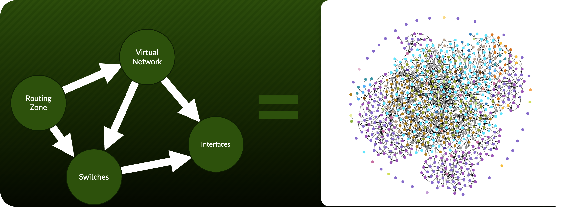
Value Point: By understanding these relationships, Apstra can determine not just what is happening but why it matters and how it affects the broader environment.
Customer Question: “When troubleshooting network issues, how much time does your team spend just trying to understand the relationships between different network elements?”
Storytelling Tip: Describe how network engineers typically maintain these relationships in their heads or in disconnected documentation. Liken Apstra to having a senior network architect constantly available who understands all these relationships and can immediately interpret what’s happening in context.
Demo Starting Point
Pre-Built Fabric Exploration
Now that we understand Apstra’s architectural foundations, let’s explore how these principles manifest in a pre-built fabric environment.
1. Accessing the Pre-Built Data Centre Fabric
Launch the Apstra web interface by navigating to https://[apstra-server-ip] in your browser. This can either be a JCL Apstra Demo or the
SE Demofound in Apstra Cloud Labs.
Value Point: This single interface provides a unified management experience across multi-vendor environments, eliminating the need to learn different tools for different network segments.
Log in using the provided demo credentials - These are provided by JCL or Cloud Labs
2. Interface Overview & Orientation
Before diving into specific features, let’s understand the interface layout:
Customer Question: “How many different interfaces does your team need to navigate to get a complete picture of your network’s health and configuration?”
Note the consistent colour coding throughout the interface:
Green: Healthy/compliant states
Amber: Warning conditions
Red: Critical issues requiring attention
Storytelling Tip: Highlight how this visual consistency reduces cognitive load on operators, allowing them to quickly assess status without parsing complex data.
3. Examining the Fabric Blueprint
Navigate to the “Blueprints” section in the left navigation panel and select the pre-built demo blueprint named “DC1_Production_Fabric”.
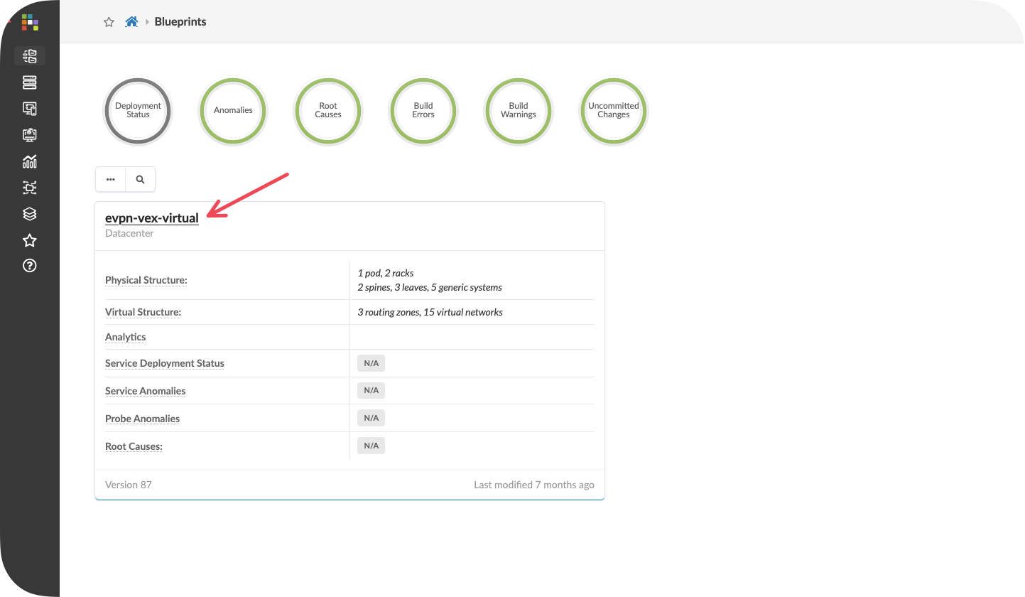
Value Point: Blueprints in Apstra represent the complete fabric intent model, encompassing all aspects of design, policy, and operational parameters in a single construct.
4. Understanding the Topology Visualization
Click on the “Visualization” tab and select “Topology” from the dropdown menu.
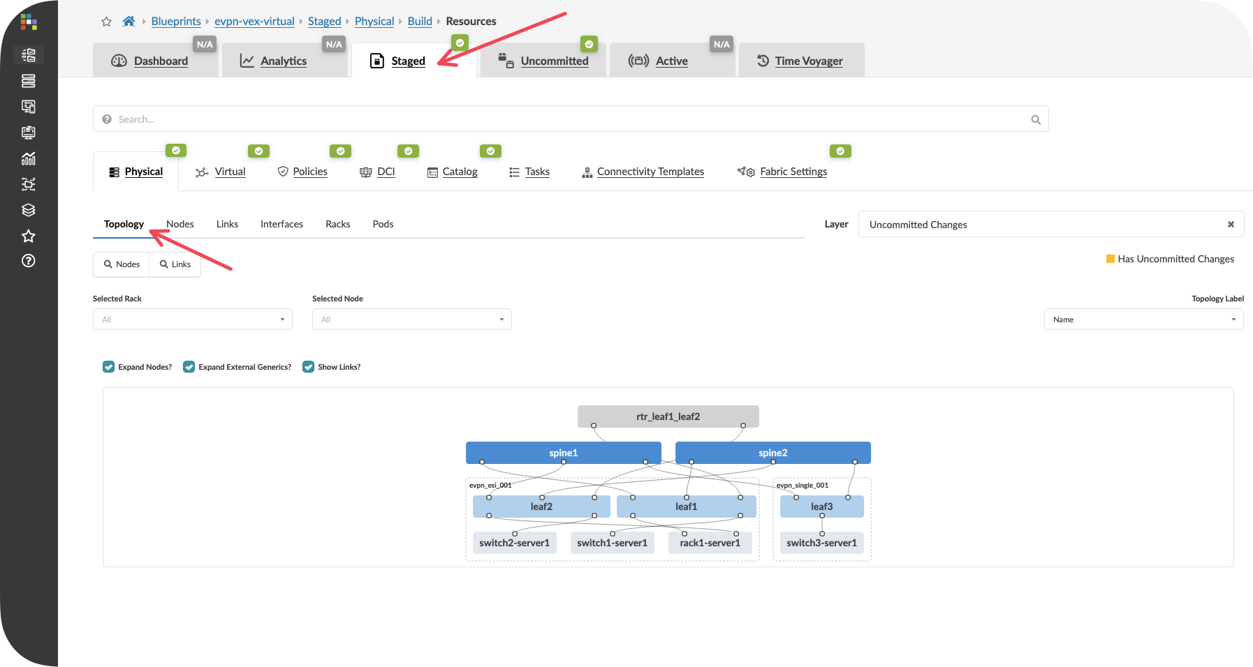
Value Point: The topology view isn’t just a network diagram—it’s a real-time representation of the network state, showing both physical connectivity and logical health.
Customer Question: “How do you currently visualize the relationship between your network design and its actual operational state?”
Storytelling Tip: Explain how this view combines what would traditionally require multiple tools—topology documentation, monitoring dashboards, and configuration management—into a single, coherent interface.
Observe how the topology illustrates the reference design principles discussed earlier, showing:
Spine-leaf architecture
Redundant connectivity paths
Server attachment points
Management network connectivity
Key Takeaways
Apstra’s architectural advantage comes from its contextual understanding of all network elements and their relationships, not just collecting data points
Intent-Based Networking transforms operations from configuration-focused to outcome-focused, aligning network management with business objectives
Reference designs balance best practices with customisation flexibility, reducing risk while meeting specific requirements
The pre-built fabric demonstrates how these principles translate into practical operational benefits
Continuous validation ensures constant alignment between intended and actual states, enabling truly proactive operations
Next Steps
In the following module, “Design Fundamentals,” we’ll explore how to create a new fabric design from scratch, building on the architectural principles introduced here. You’ll learn how Apstra’s reference design methodology guides users through creating validated designs while maintaining flexibility for specific business requirements.
Design Fundamentals
Understanding the Three-Stage Clos Topology in your lab
Objectives
Understand the three-stage Clos spine-leaf topology and its benefits
Explore how Apstra models both managed and unmanaged network elements
Examine the rack-based design approach and its relationship to physical data centre layout
Learn how templates combine rack designs with spine infrastructure to create complete fabric blueprints
Understanding the Topology Structure
1. The Three-Stage Clos Architecture
The demonstration environment showcases a three-stage Clos network, which has become the de facto standard for modern data centre design. This topology consists of three distinct layers:
Spine Layer: The spine switches (spine1 and spine2) form the backbone of the fabric, providing high-bandwidth connectivity between all leaf switches. Each spine connects to every leaf switch, creating multiple equal-cost paths throughout the network.
Leaf Layer: The leaf switches (leaf1, leaf2, and leaf3) provide connectivity to servers, storage, and other endpoint devices. Each leaf connects to all spine switches, ensuring redundant paths for all traffic flows.
Endpoint Layer: The connected devices represent the actual workloads and services that the network supports.
Value Point: This architecture provides predictable performance, simplified operations, and linear scalability—you can add capacity by simply adding more leaf switches without redesigning the entire network.
Storytelling Tip: Compare the spine-leaf design to a well-designed motorway system where multiple routes exist between any two destinations, ensuring traffic can flow efficiently even if one route becomes congested or unavailable.
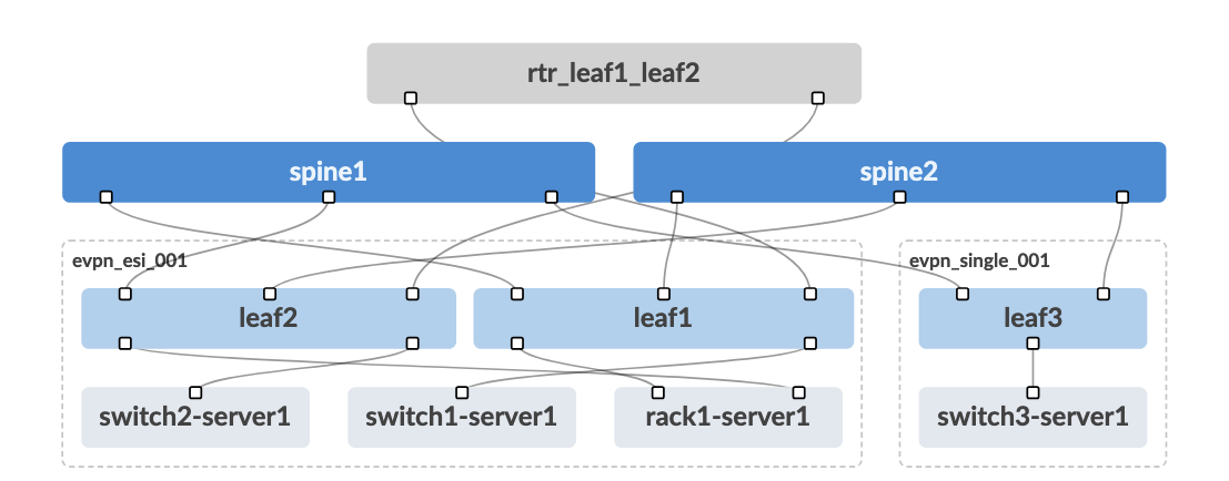
2. Managed vs. Unmanaged Elements
Looking at the topology diagram, you’ll notice elements in different colours representing Apstra’s approach to network modelling:
Blue Elements (Managed Devices): The spine and leaf switches shown in blue represent infrastructure that Apstra directly manages. These devices receive their configurations from Apstra and report their status back to the system continuously.
Grey Elements (Generic Systems): The grey elements represent devices that Apstra needs to understand for connectivity modelling but doesn’t directly manage. These fall into two categories:
External Generic Systems: Located above the spine switches, these represent external connectivity such as campus networks, MPLS backbones, or data centre interconnect circuits
Generic Systems: Located below the leaf switches, these represent servers, storage devices, network appliances, and other endpoint equipment
Value Point: This modelling approach allows Apstra to maintain complete network awareness whilst respecting operational boundaries—understanding what connects where without requiring management access to every device.
Customer Question: “How do you currently track and model the relationship between your network infrastructure and the servers and applications it supports?”
Storytelling Tip: Explain how Apstra acts like an air traffic control system that needs to know about all aircraft in its airspace (both those it controls and those it simply tracks) to ensure safe and efficient operations.
3. Rack-Based Design Philosophy
The dotted lines surrounding certain leaf switches represent racks, which form the fundamental building blocks of Apstra’s design methodology. This approach mirrors how data centres are actually constructed and operated:
Physical Reality: When you walk into a data centre, you see rows and rows of racks. Each rack typically contains:
One or two top-of-rack switches (the leaf switches)
Multiple servers, storage devices, or appliances
Power distribution and environmental monitoring equipment
Customer Question: “How easily can your team correlate network issues with specific physical locations in your data centre?”
Storytelling Tip: Compare this to how building architects design office spaces—they don’t just think about individual desks and chairs, but about how they’re organised into departments and floors, understanding both the individual components and their logical groupings.
Design Methodology Overview
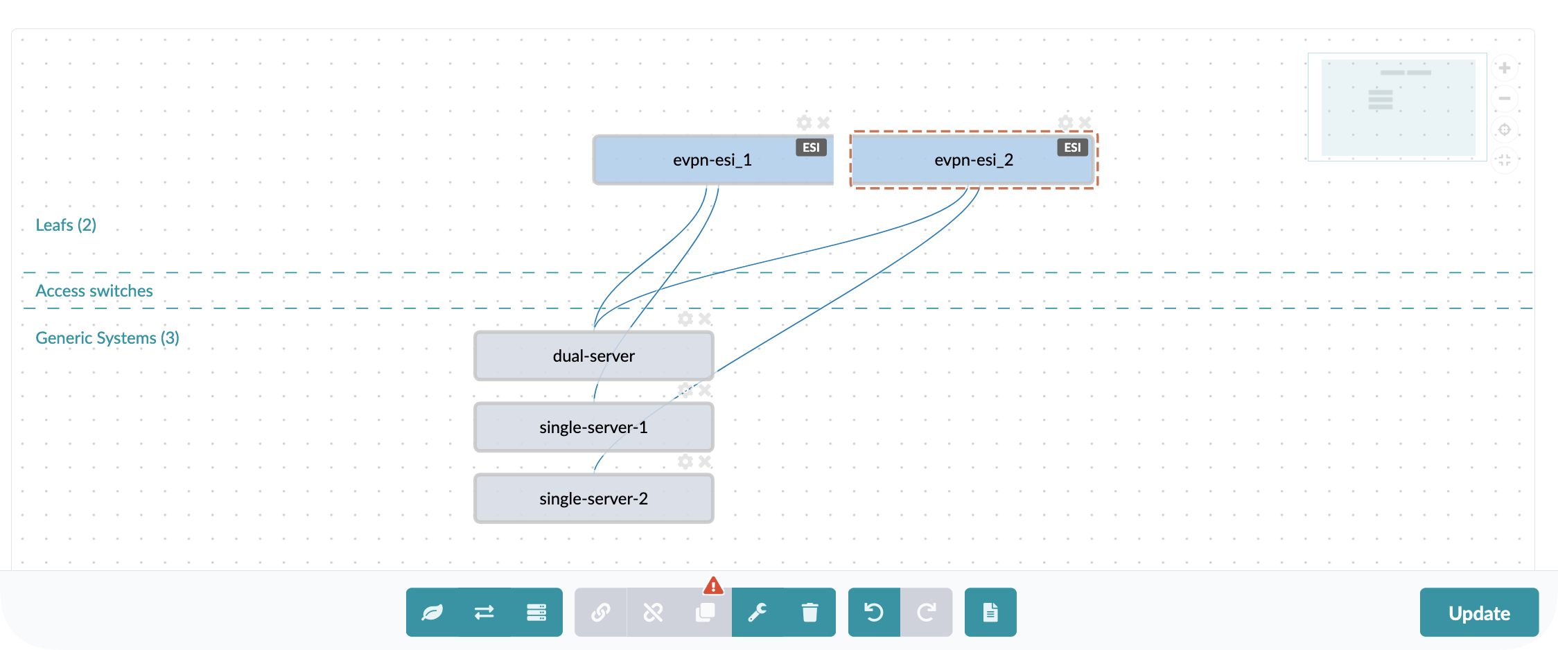
1. The Design Tab Interface
Within the Apstra interface, the Design tab provides the tools for creating and modifying network blueprints using a visual, intuitive approach:
Drag-and-Drop Simplicity: The interface resembles familiar design tools like Visio, allowing network architects to create rack designs by dragging and dropping components into place. This visual approach reduces the learning curve and makes design intent immediately clear to stakeholders.
Value Point: By making network design visually intuitive, Apstra enables better collaboration between network teams, facilities teams, and business stakeholders who need to understand the proposed architecture.
Customer Question: “How do you currently communicate network design decisions to non-technical stakeholders who need to approve infrastructure investments?”
Storytelling Tip: Highlight how visual design tools have transformed other industries (architecture, automotive, aerospace) by making complex technical concepts accessible to broader audiences, and how Apstra brings this same approach to networking.
2. Rack Design Components
An important concept in Apstra is that everything is designed in a vendor-neutral way. During the design process, the user simply defines how many ports of what speed they want, and then they can select the accompanying hardware later, meaning that users can build their network without limiting themselves to one single vendor or platform.
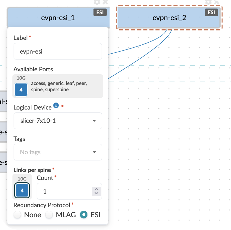
Individual rack designs define the relationship between:
Top-of-rack switch models and configurations
Server connectivity patterns and port assignments
Redundancy and failover requirements
Value Point: Standardising rack designs ensures consistency across deployments whilst allowing for different rack types optimised for specific workloads (compute-intensive, storage-heavy, GPU clusters, etc.).
Customer Question: “How do you ensure consistency in server connectivity and network access policies across different areas of your data centre?”
Storytelling Tip: Compare rack standardisation to manufacturing assembly lines where standardised components and processes ensure quality and predictability whilst still allowing for different product variations.
3. Template-Based Fabric Creation
Templates in Apstra combine one or more rack designs with spine infrastructure specifications to create complete fabric blueprints:
Composition Approach:
Choose your rack designs
Specify the number and type of spine switches required
Apply global policies
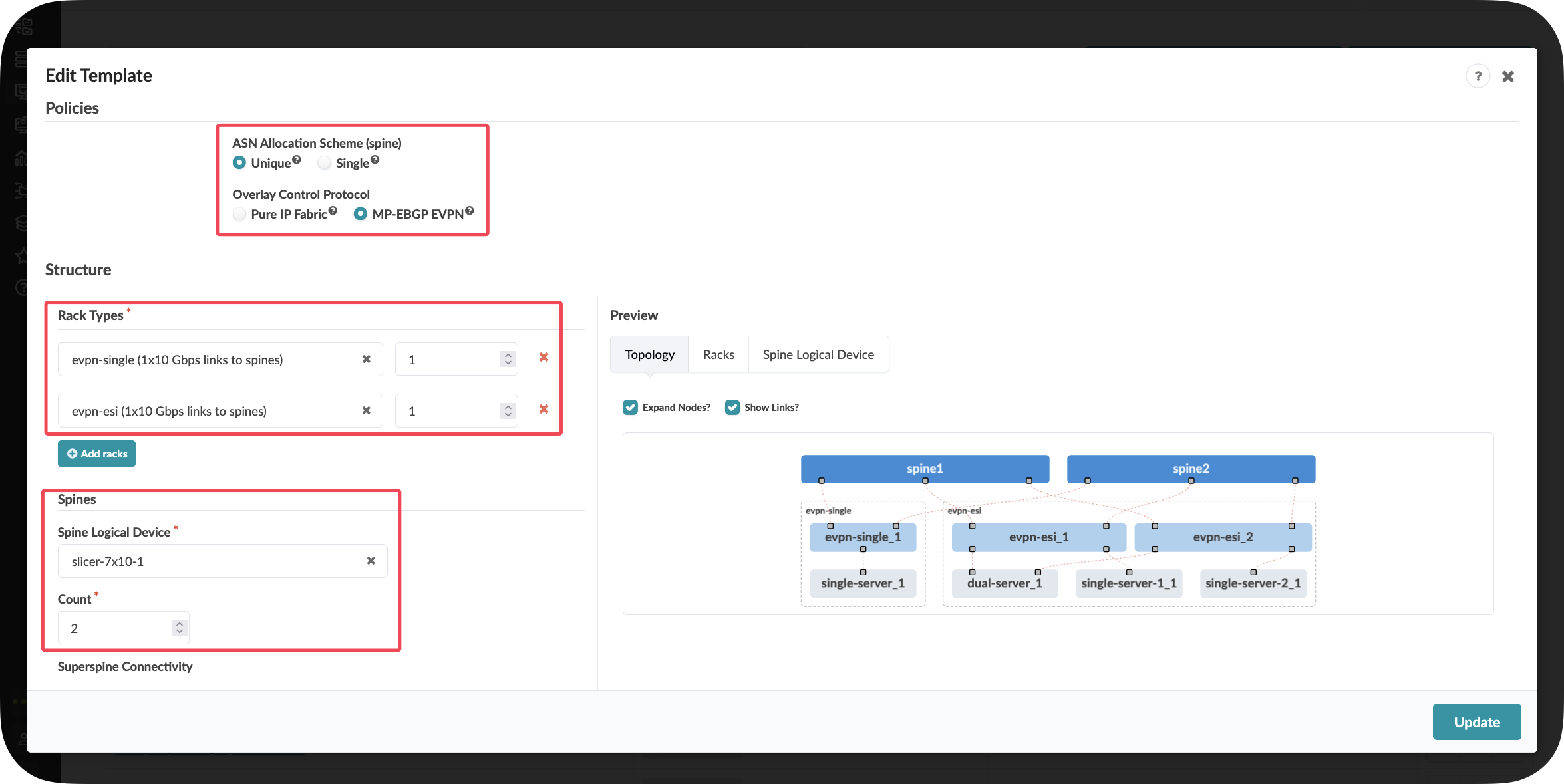
Scalability Planning: Templates make it easy to model different fabric sizes—from a small fabric with a few racks to a large-scale deployment with hundreds of racks—using the same fundamental building blocks.
Value Point: This compositional approach accelerates design processes whilst ensuring that all deployments follow validated architectural patterns, reducing both design time and deployment risk.
Customer Question: “How long would it take your team to design and validate a new data centre fabric or a significant expansion today?”
Storytelling Tip: Describe how templates function like architectural blueprints that can be scaled up or down depending on the building size whilst maintaining the same structural integrity and design principles.
Key Takeaways
The three-stage Clos topology provides the foundation for scalable, predictable data centre networking
Apstra’s modelling of both managed and unmanaged elements creates complete network awareness whilst respecting operational boundaries
Rack-based design philosophy aligns logical network constructs with physical data centre reality
Template-driven fabric creation accelerates deployment whilst ensuring architectural consistency
Visual design tools make network architecture accessible to broader stakeholder communities
The compositional approach enables both standardisation and customisation to meet specific requirements
Day 2 Operations: Data Centre Expansion and Virtual Network Creation
Section 1: Physical Expansion - Adding Data Centre Capacity
Business Context
Speed kills deals. When customers need new services deployed, every day of delay represents lost revenue opportunity. Traditional data centre expansion processes that take weeks now become competitive disadvantages in markets where agility determines winners.
Customer Story: A major cloud service provider recently shared: “We’d lose deals because provisioning took months. Last month, a project needed services within days. With Apstra deployed seamlessly, and closed the deal. That’s business agility that drives revenue.”
Demonstration Objectives
Show how physical capacity expansion works in Apstra
Demonstrate pre-staging capabilities that eliminate deployment delays
Illustrate automatic resource allocation and configuration generation
Highlight the business impact of rapid infrastructure deployment
Scenario: Adding Capacity for the Big Data Analytics Service
[!NOTE] This is a scenario I often use if I do not know the customer just to help them visulise what I am showing and how it could look in there environment.
Your company has just greenlit a new Big Data Analytics service offering for customers. The first task is to expand the physical capacity of your data centre by adding a new rack of switches and servers to support the increased compute requirements.
Value Point: Traditional rack additions require extensive planning and manual configuration. Apstra allows you to pre-stage entire rack deployments before hardware even arrives, eliminating the typical weeks-long provisioning cycle.
Customer Question: “What’s the process today when a change is needed in the data centre? How much time does your team currently spend validating that network changes have been implemented correctly?”
Task: Add a New Rack to Your Data Centre
Reflection Point: Traditional Approach Challenges
Before we begin, consider what this involves in a traditional data centre:
Planning Phase: How would a customer provision a new pair of switches from scratch?
Consistency Challenge: How would they ensure consistency with existing network configurations?
Time Investment: How long would it take them to:
Plan IP addressing and ASN assignments
Configure basic switch setup (management, credentials)
Configure underlay protocols (BGP)
Configure overlay protocols (EVPN, VXLAN)
Test connectivity
Troubleshoot issues
Industry Reality: Many organisations report this process taking days or even weeks for a single rack addition when done manually.
Storytelling Tip: Share how network provisioning bottlenecks directly impact business outcomes. One data centre provider transformed their delivery time from 8-12 hours of manual work to 30 minutes, eliminating the delivery constraint that was losing them competitive deals.
Step-by-Step Demonstration
Step 2: Add a New Rack to the Blueprint
The easiest and fastest way to expand your network is to add a rack:
Navigate to Staged > Physical > Racks
Click the Add Racks button (+)
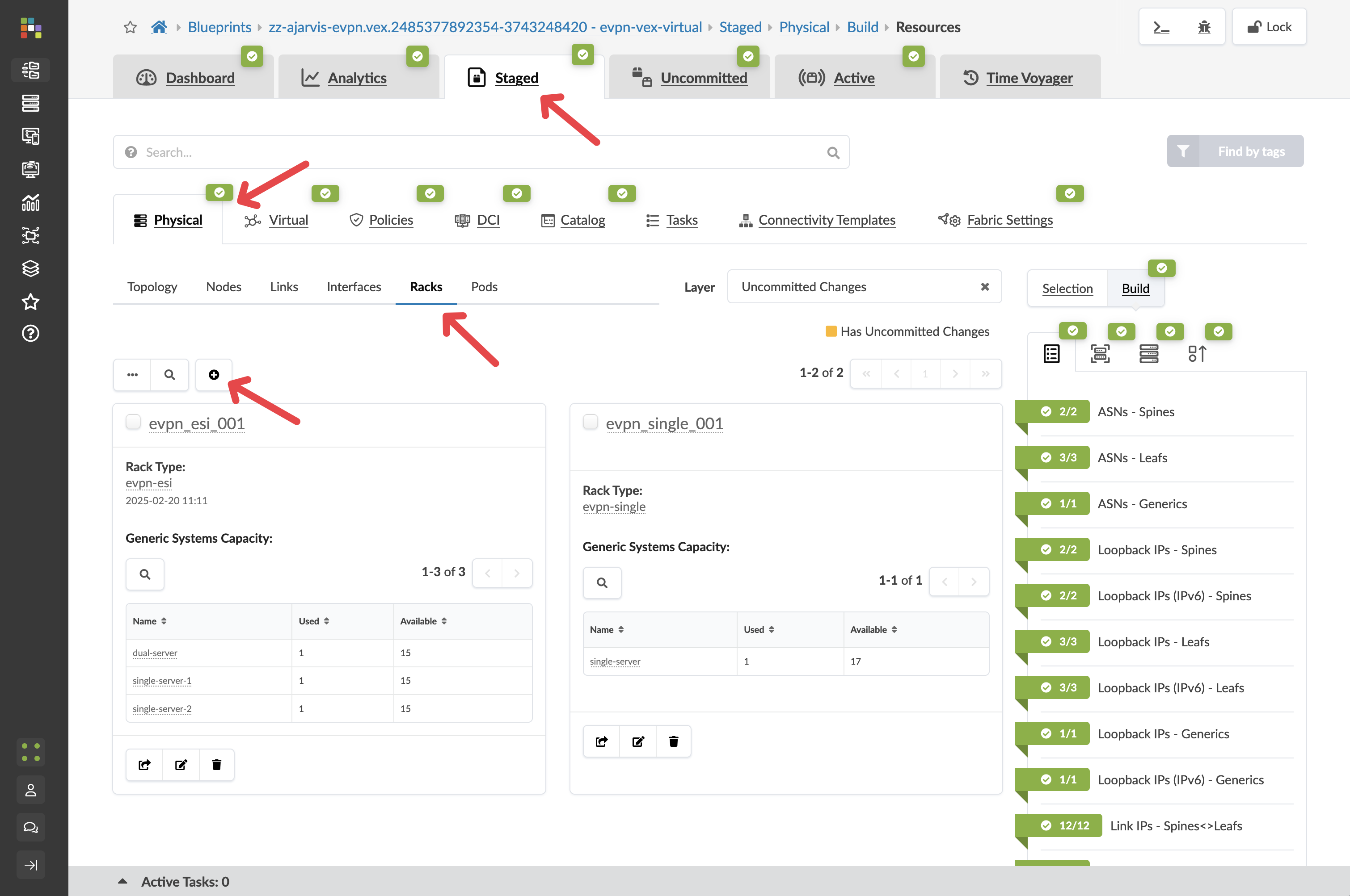
From the Rack Type drop-down list, select L2 Virtual Dual (the dual-switch rack can allow you to showcase the multivendor aspects of Apstra)
Leave the number of racks at 2
Value Point: Notice how Apstra tells you how many racks can be added, it will continually validate that what the user wants to do is actually possible.
Click Add to stage the rack addition and return to the topology view
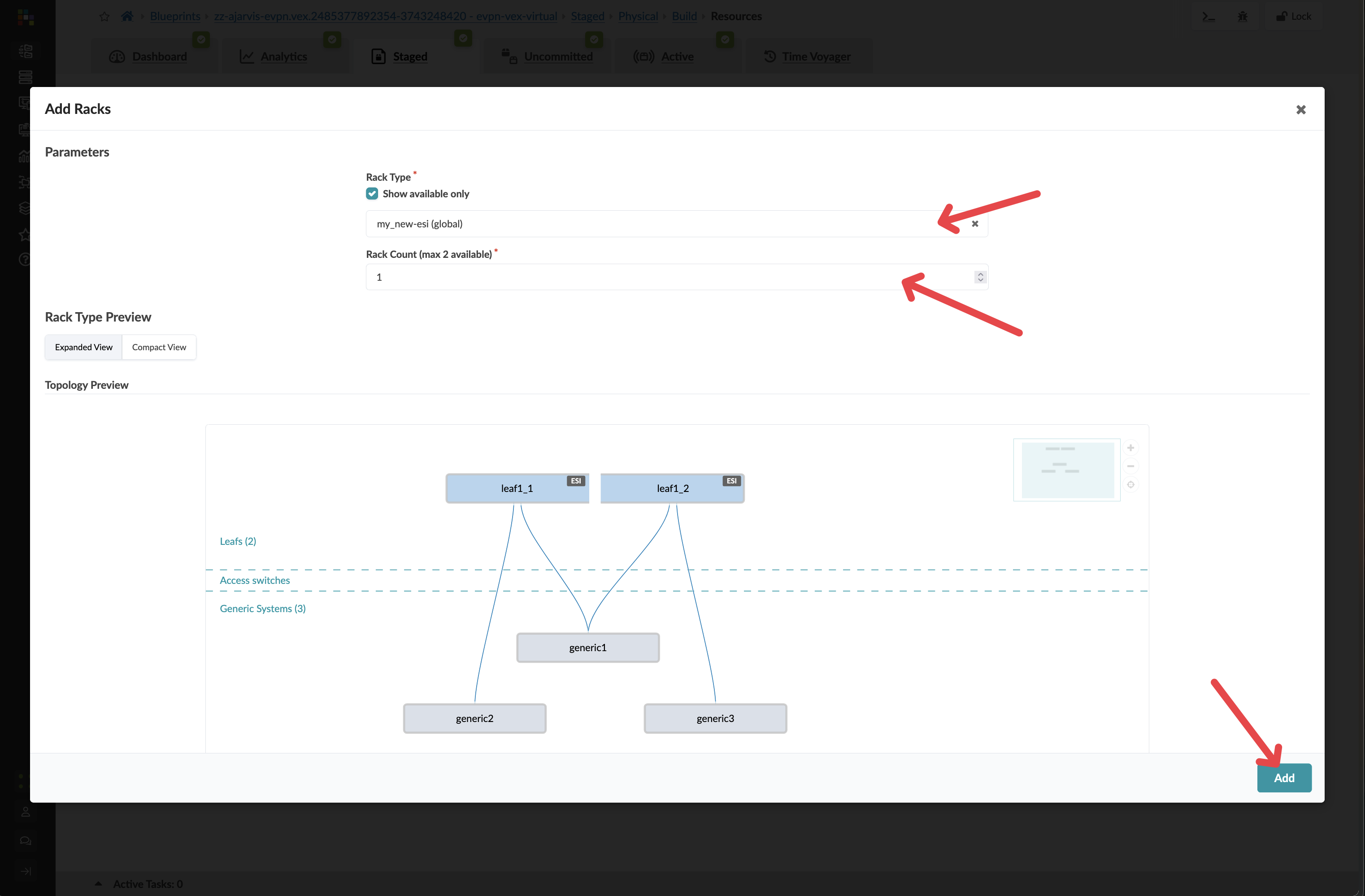
Key Insight: At this point, you’ve just pre-staged a rack addition without needing any physical hardware. Apstra allows you to plan and prepare your network expansion before the physical switches even arrive in your data centre.
Customer Question: “When you are asked to onboard a new customer, how long does that take? How much time does it normally take the network team to provision infrastructure for a project?”
Storytelling Tip: Emphasise the competitive advantage of pre-staging. One customer eliminated their network provisioning bottleneck entirely – the same service that previously took 30 minutes to configure now takes just 30 seconds to deploy when hardware arrives.
Step 3: Let Apstra Handle Resource Allocation
When you add a new rack, you will need to add new IPs and ASNs. Apstra does this for you, taking the next items from your resource pools.
You don’t need to do a thing – it does it for you
Value Point: Manual IP and ASN management is error-prone and time-consuming. Apstra’s automatic resource allocation eliminates configuration conflicts and reduces deployment time from hours to seconds.
Step 4: Assign Device Profiles
Navigate to Staged > Physical > Device Profiles
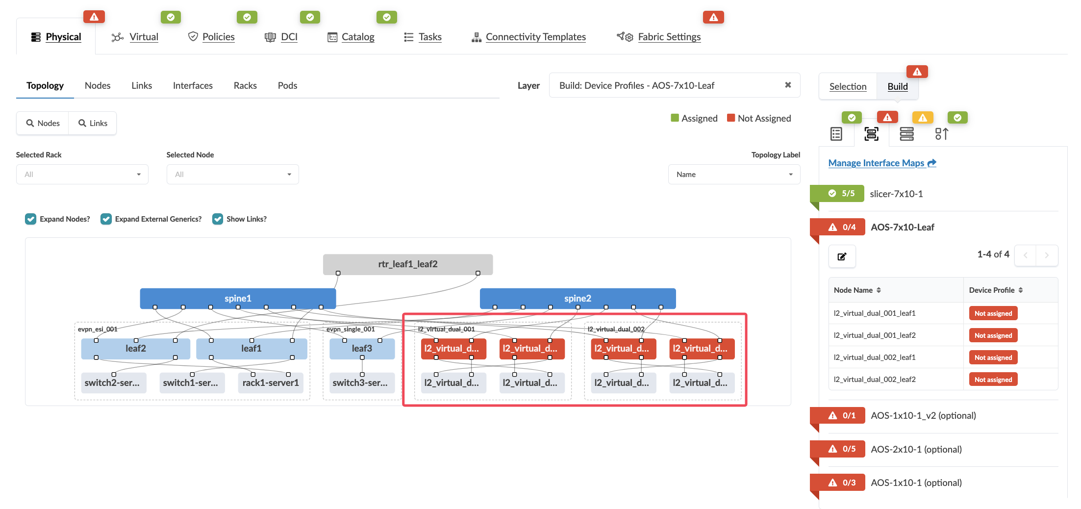
If there are any red indicators for your new leaf switches, click them, then click Change interface maps assignment
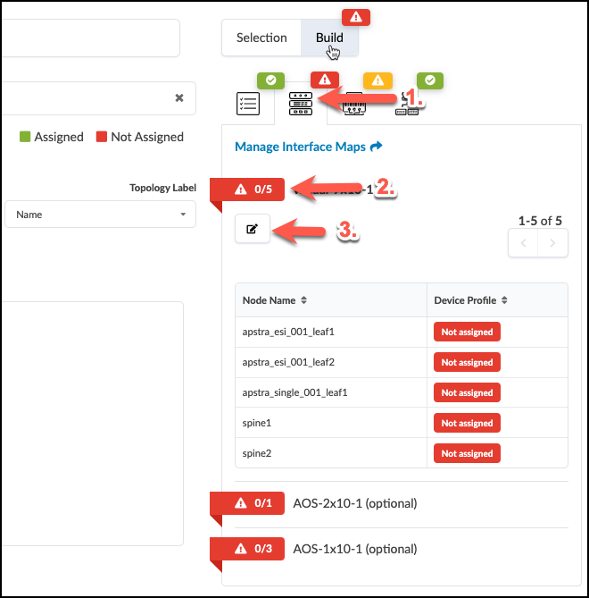
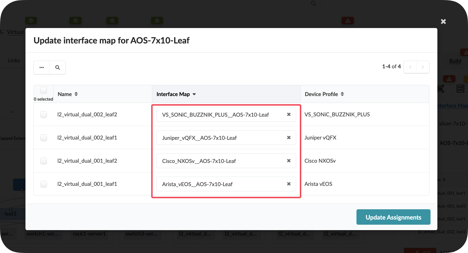
Select one of each vendor as the interface map for your new leaf switches
Click Update Assignments
Value Point: Device profiles ensure consistent hardware configurations across your entire fabric. This eliminates the manual effort of mapping interfaces and ensures standardisation across different hardware vendors.
Step 5: Review and Commit Your Changes
Click the Uncommitted tab to see all your staged changes
Take a moment to review what Apstra is preparing for you. Notice how the system has automatically:
Created a plan for assigning unique ASNs to the new devices
Prepared IP addressing for all interfaces
Set up BGP peering configurations between the new leaf switches and existing spine switches
Prepared EVPN configurations for the overlay network
After reviewing, enter a commit message like “Pre-staged new analytics rack” and click Commit
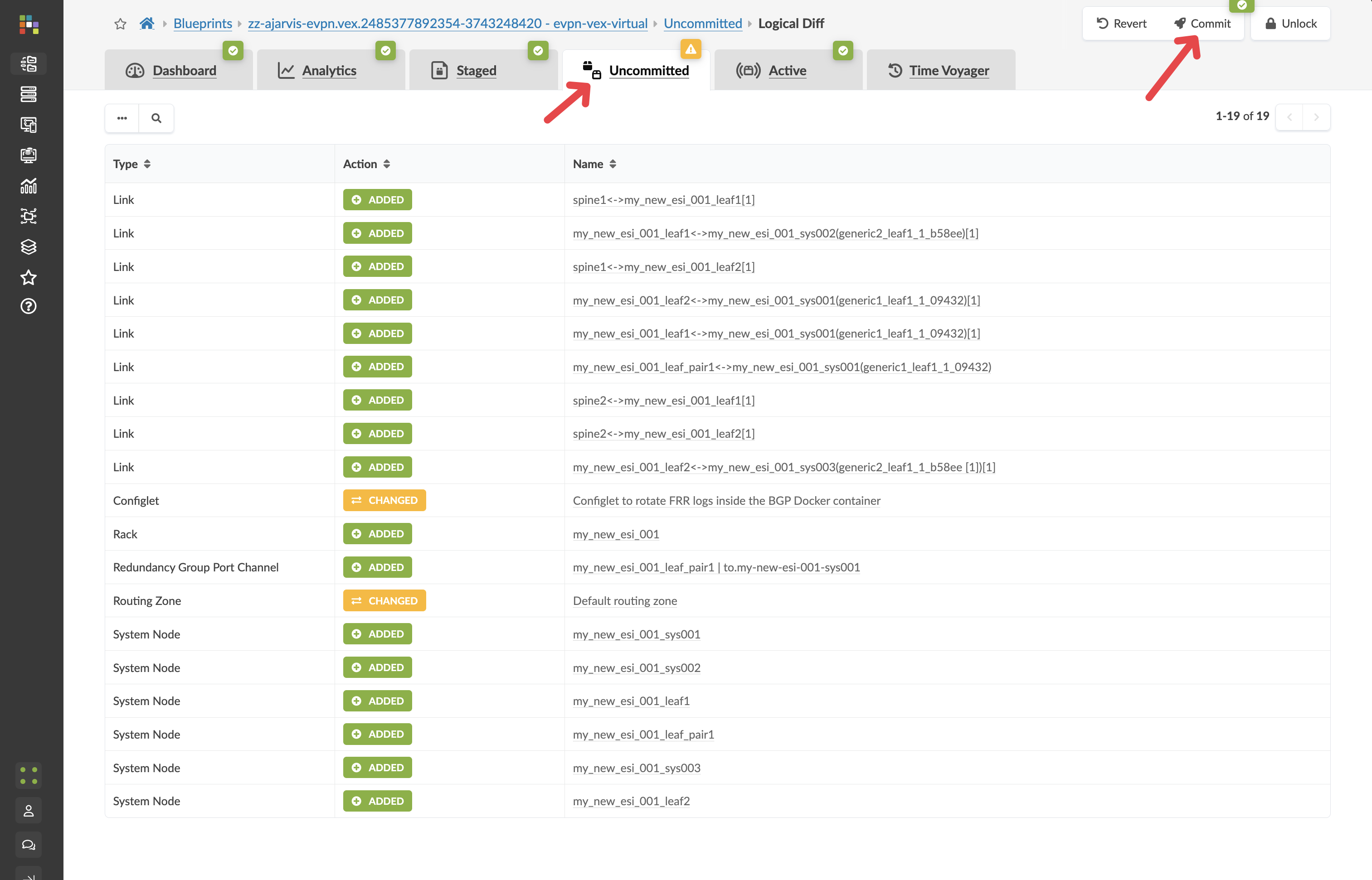
Value Point: The commit process provides full audit trails and change management. Every modification is tracked, allowing for complete visibility into who made what changes and when.
Step 6: Understanding the Power of Pre-staging
What makes this workflow revolutionary is that:
No physical devices needed yet: You’ve pre-staged the entire configuration before the physical switches even arrive at your data centre
Instant deployment when hardware arrives: When the physical switches do arrive, you simply:
Rack and cable the switches according to your design
Add the devices to Apstra’s management (ZTP or Simple Manual On-boarding)
Map them to the pre-staged leaf switches in your blueprint
The full configuration will be pushed to them in seconds The new switches will be fully deployed, configured, and monitored as part of your fabric immediately
Network-wide consistency: All existing devices that need to communicate with these new switches will be automatically updated to include them in the fabric
Customer Story: A co-location provider shared: “Our network had become the bottleneck. Service delivery always got stuck at the network layer. We can now deliver services to customers the same day now or next day at worst, rather than waiting days or weeks for network provisioning.”
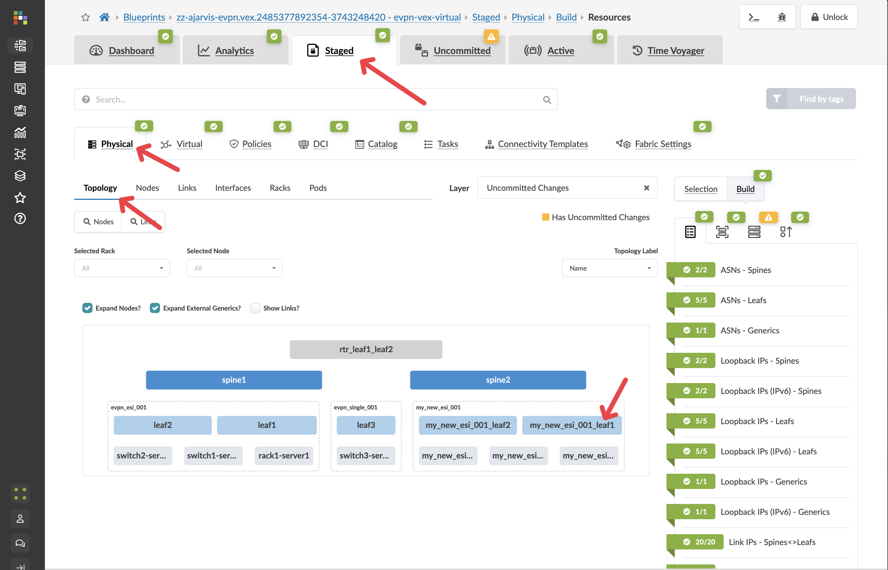
Step 7: Examine the Prepared Configuration
Let’s look at what Apstra has prepared:
Navigate to Staged > Physical > Topology
Find one of your newly added leaf switches and click on it
Click on the Rendered Configuration tab
Review the complete configuration that Apstra has generated. Notice:
Basic system configuration
Interface configurations
BGP underlay configuration
EVPN overlay configuration
All IP addressing
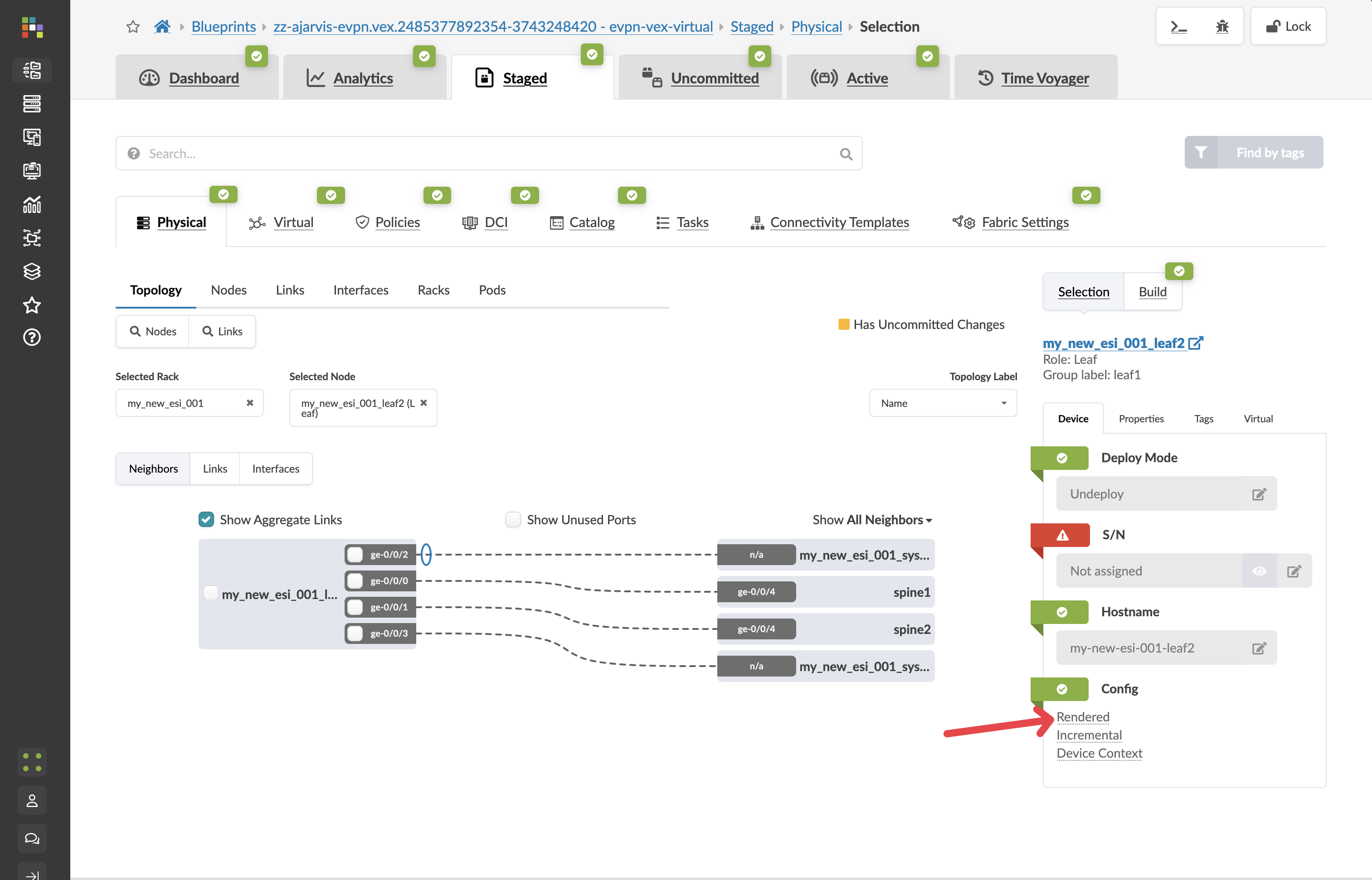
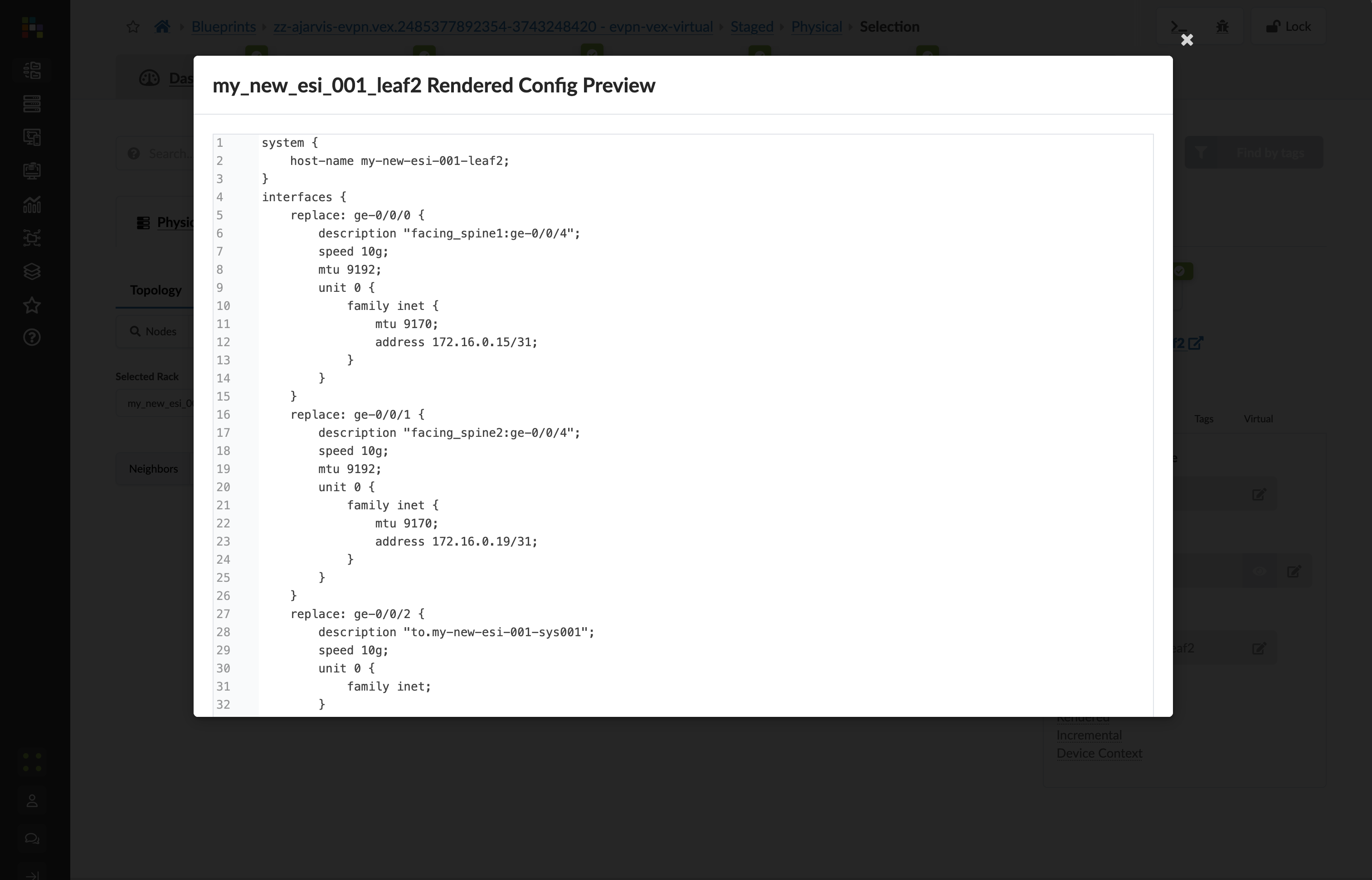
Value Point: This entire configuration was generated automatically because Apstra understands your network as a complete system. When the physical devices are added, this configuration will be deployed to them, and the system will also automatically update configurations on the spine switches to establish BGP sessions with these new devices.
What You’ve Accomplished
In just a few minutes, you’ve:
Pre-staged a new rack with redundant leaf switches to your data centre
Created a plan for all necessary resources (ASNs, IP addresses)
Generated complete device configurations that will be ready when the hardware arrives
Prepared updates for existing devices to incorporate the new rack into the fabric
Business Impact: In a traditional networking environment, this entire process would require extensive planning, manual configuration, and troubleshooting once the hardware arrives. With Apstra, you can prepare everything in advance and deploy instantly when hardware is available.
ROI Discussion Point: Consider the cost of delayed service delivery. If each day of delay represents potential lost revenue, Apstra’s pre-staging capabilities can directly impact your bottom line by eliminating deployment bottlenecks.
Section 2: Logical Expansion - Creating Virtual Networks
Business Context
From bottleneck to advantage. Network provisioning processes that previously constrained business growth now become competitive differentiators. When customers expect same-day service delivery, your network infrastructure should accelerate, not impede, business objectives.
Customer Story: A data centre operator explained: “Particularly in the data centre, customers would order services and then wait days or weeks for network provisioning. With Apstra, we can hand over services to customers the same day now or next day at worst.”
Demonstration Objectives
Show rapid virtual network creation and deployment
Demonstrate both Layer 2 and Layer 3 network configurations
Illustrate automatic VXLAN and routing configuration
Highlight the business value of accelerated service delivery
Scenario: Building Network Tiers for the Big Data Analytics Service
With our physical capacity expanded, we now need to establish the network segments for our Big Data Analytics service. This service requires two separate network tiers:
A web-facing tier for the analytics dashboard and user interface, which requires extra security controls
A backend tier for the database and processing components
In Apstra, we’ll implement these as virtual networks within our Analytics routing zone.
Value Point: Traditional virtual network creation involves complex manual configuration across multiple devices. Apstra transforms this into a simple declaration of intent, automatically handling all implementation details.
Customer Question: “How much time does it normally take the network team to provision infrastructure for a project? When you are asked to onboard a new customer, how long does that take?”
Task: Create Virtual Networks for the Analytics Service
Reflection Point: Traditional Complexity
In traditional networking, creating virtual networks would involve:
Configuring VLANs on each relevant switch
Setting up VXLAN VNIs and mappings
Configuring L2/L3 boundaries
Ensuring consistent configuration across devices
Manually tracking which segments are deployed to which racks
This process becomes exponentially complex as your network grows.
Storytelling Tip: Emphasise how Apstra eliminates the manual coding and stress of being the bottleneck that holds up customer commitments. One customer reduced their provisioning time from hundreds of lines of code to a simple service template.
Step-by-Step Demonstration
Step 1: Create the Analytics Web Tier Network (Layer 2 Only)
From the SE Demo blueprint, navigate to Staged > Virtual > Virtual Networks
Click Create Virtual Network
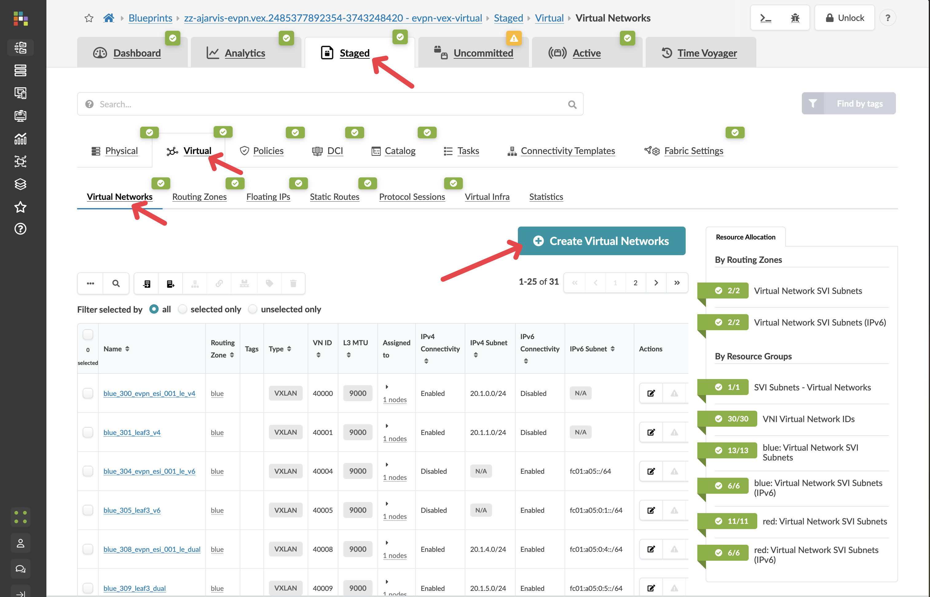
Configure the network with these settings:
Parameter |
Value |
|---|---|
Type |
VXLAN |
Name |
analytics-web |
Routing Zone |
red |
IPv4 Connectivity |
Disabled |
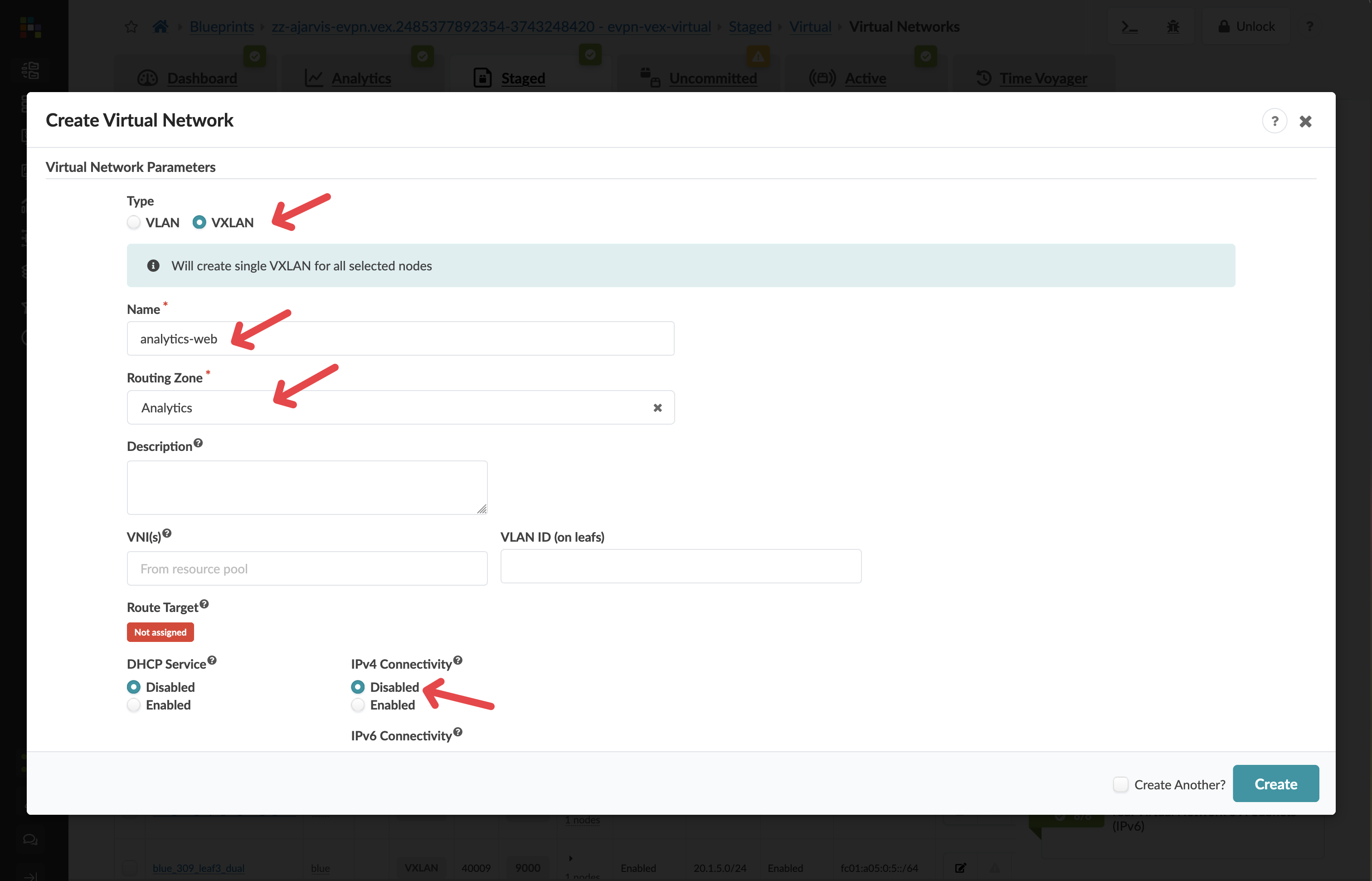
Security Design Decision: By disabling IPv4 Connectivity, we’re creating a Layer 2 only network (bridged overlay). This means:
The gateway for this network will reside on an external firewall, not on the leaf switches
This provides enhanced security for our customer-facing web tier, allowing for additional inspection and filtering of traffic
All inter-VLAN routing will pass through the firewall where security policies can be enforced
In the Assigned To section, select all racks in your fabric
Value Point: While you have the flexibility to deploy virtual networks selectively, in this case we want the web tier available across the entire fabric to allow for flexible workload placement.
Click Create to create the virtual network
Step 2: Create the Analytics Database Tier Network (Layer 3)
Click Create Virtual Network again
Configure the network with these settings:
Parameter |
Value |
|---|---|
Type |
VXLAN |
Name |
analytics-db |
Routing Zone |
red |
IPv4 Connectivity |
Enabled |
IPv4 Subnet |
10.1.2.0/24 |
Virtual Gateway IP |
10.1.2.1 |
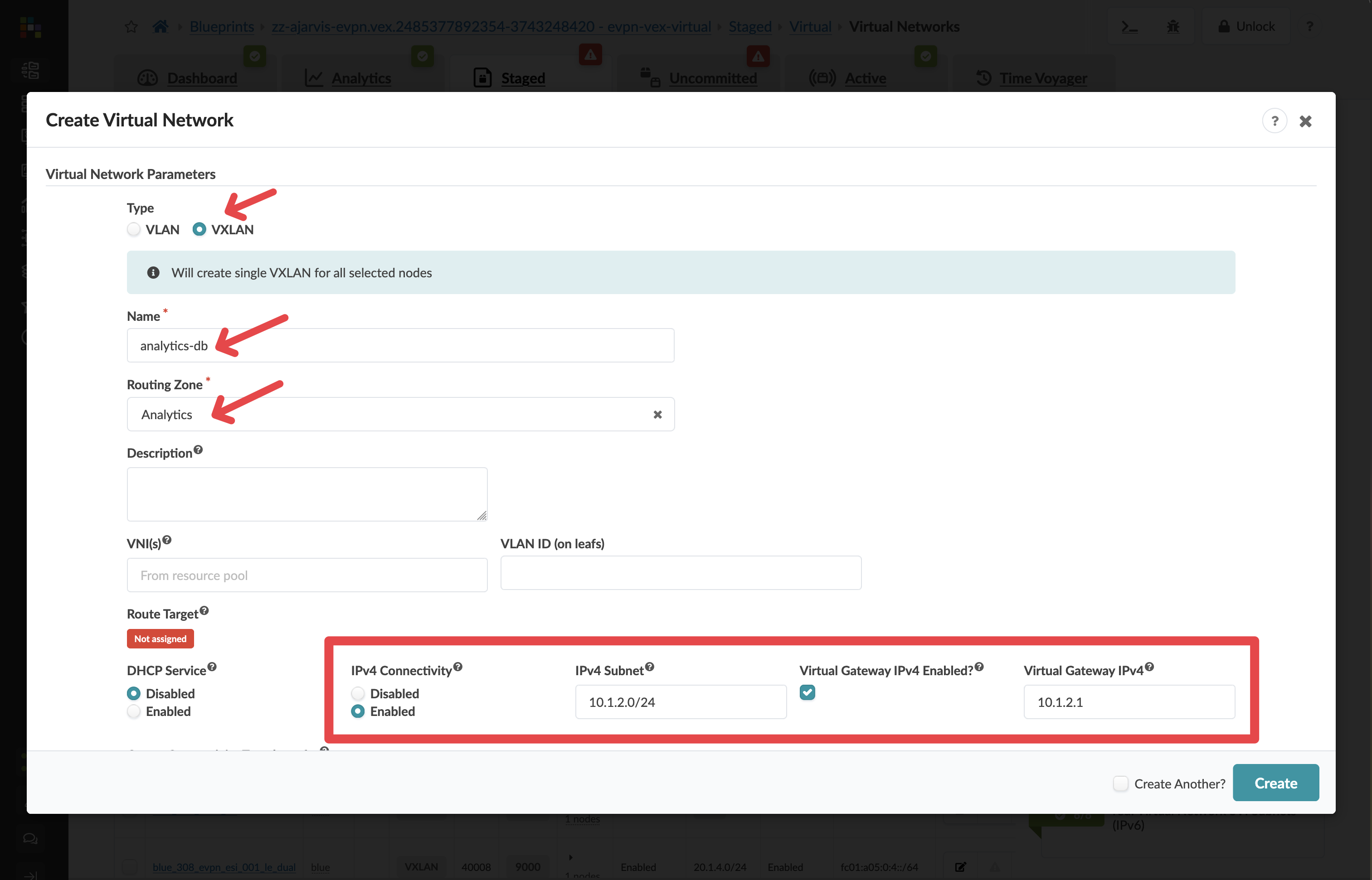
Network Design Note: For this network, we’ve enabled Layer 3 functionality:
This creates a gateway (10.1.2.1) directly on the leaf switches
Traffic can be routed between this network and others in the same routing zone
Instead of manually entering the subnet, you could have selected an IP pool, which would automatically assign the next available subnet from that pool
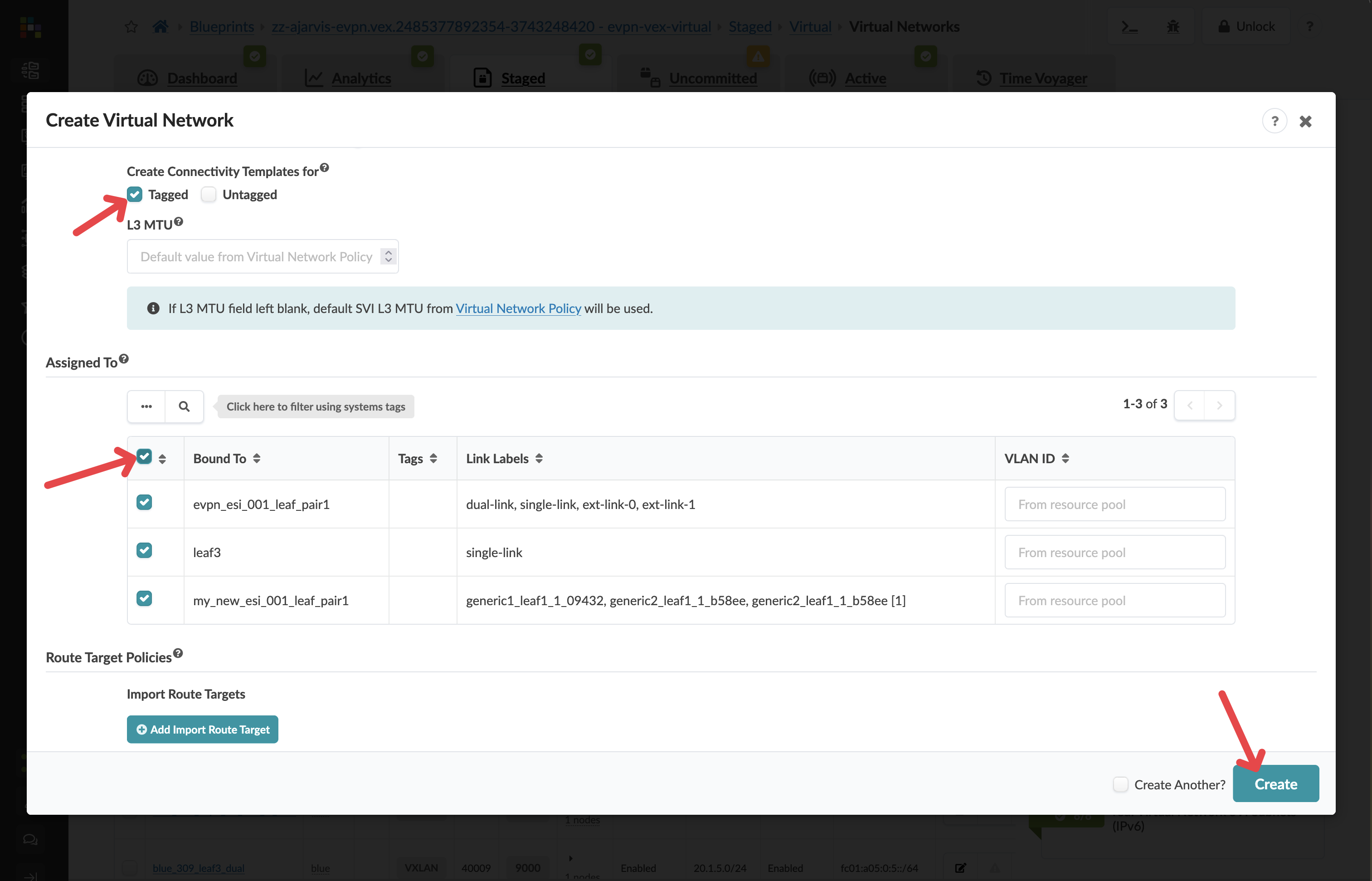
In the Create Connectivity Templates for section, select Tagged
In the Assigned To section, select all racks in your fabric
Click Create to create the second virtual network
Step 3: Assign Resources to Virtual Networks
There should not be any needed after creating the virtual networks. Apstra will identify any resources that need to be assigned:
If there are any red resource indicators, click them and assign the appropriate pools
Click Save to complete the assignments
Step 4: Assign Resources to the Routing Zone
After creating the virtual networks to switches, Apstra will identify any resources that need to be assigned under the routing zone:
Why? Previously we added the routing zone, but the configuration was never pushed because no virtual network using that routing zone existed. Now we’re actually pushing our virtual networks to every switch. The fabric requires loopbacks in order to operate.
If there are any red resource indicators in the Virtual Network or Routing Zone tabs, click them and assign any of the pools
Click Save to complete the assignments
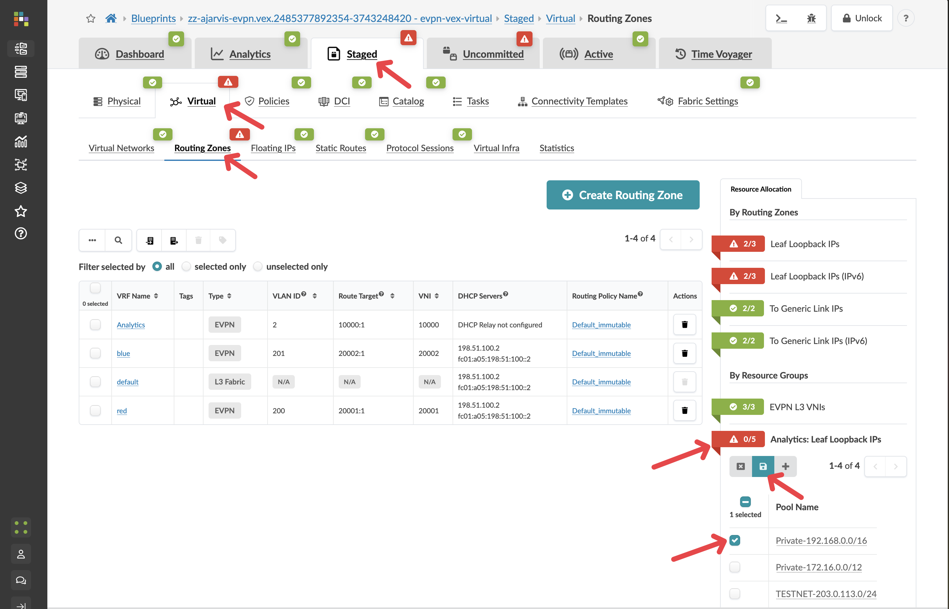
Apstra has now auto-assigned all of the needed loopback addresses.
Value Point: Automatic resource management eliminates the manual tracking and allocation that typically causes configuration conflicts and deployment delays.
Step 5: Review and Commit Your Changes
Before you commit on your blueprint, let’s examine how Apstra has automated the complete configuration of your devices:
Navigate to Staged > Physical > Devices
Select one of your leaf switches by clicking on it
Click on the Incremental Configuration tab
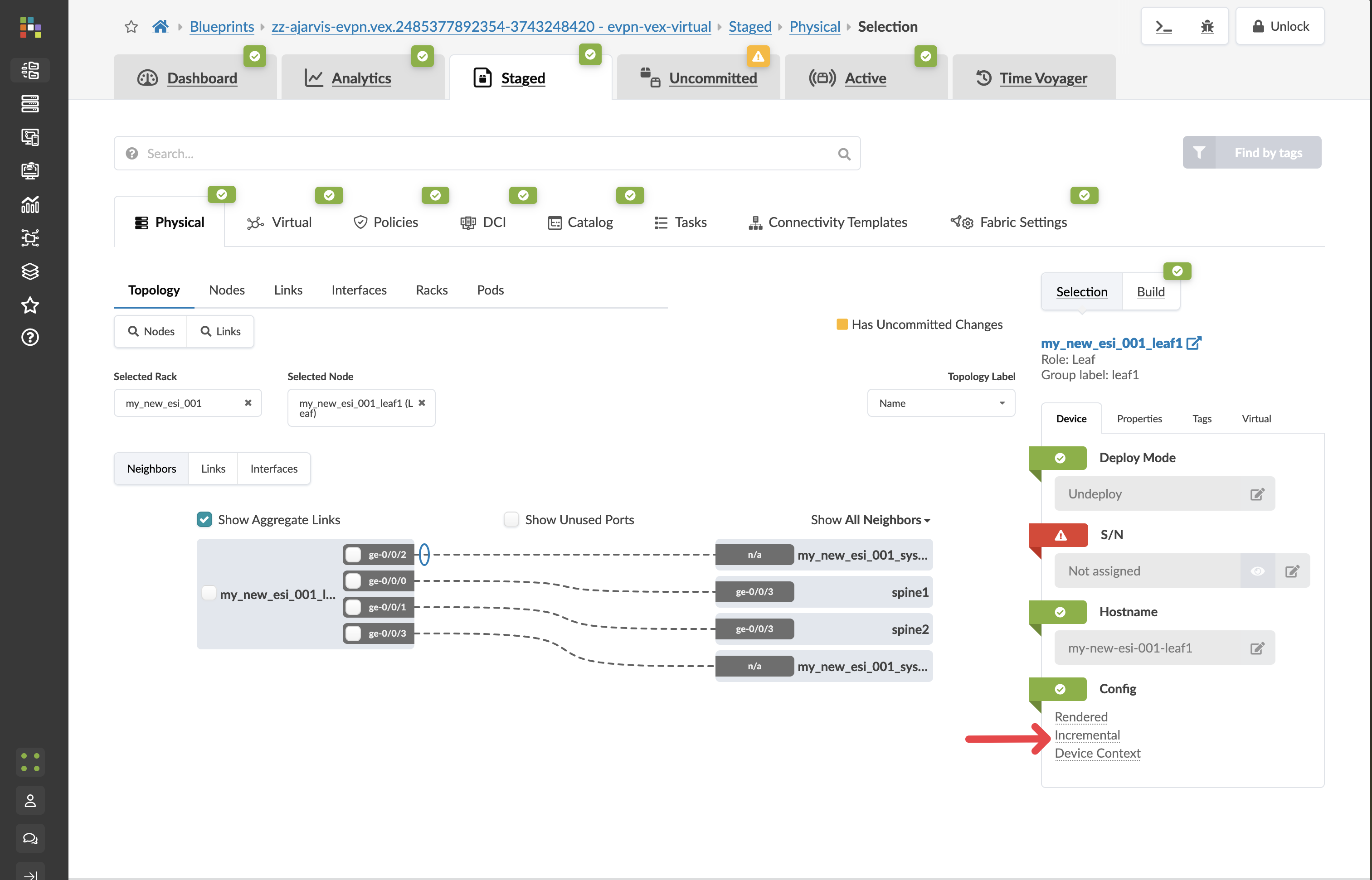
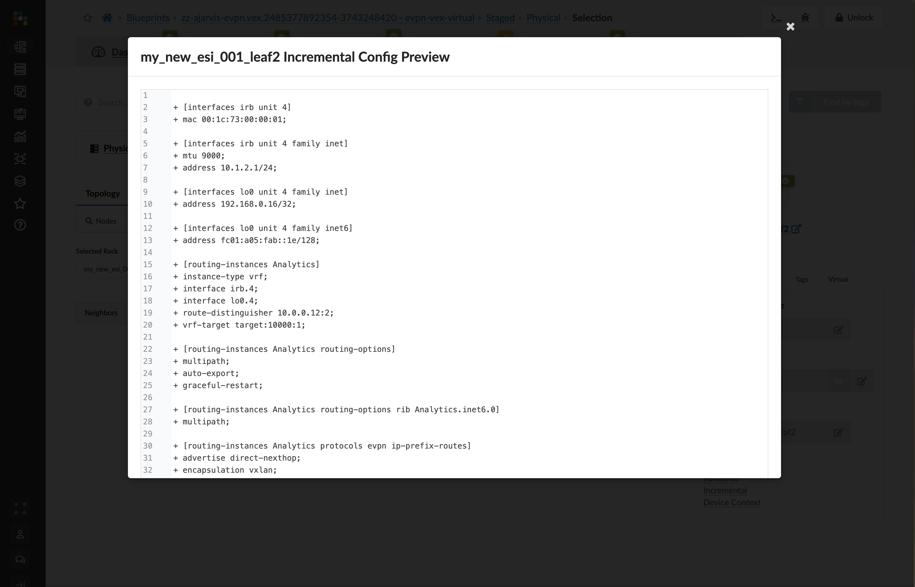
This will show you all of the incremental configuration that has been generated based on the very few clicks you’ve had to do. You have successfully now deployed a new VRF and multiple VXLAN overlays, not to mention the adjustments that are needed to the EVPN protocol configuration.
Value Point: What you see here represents hundreds of lines of configuration that would typically require hours of manual coding and testing. Apstra generated this automatically from your simple intent declarations.
Click the Uncommitted tab to see your staged changes
Enter a commit message like “Added Analytics virtual networks” and click Commit
Customer Story: One customer shared: “Eight to twelve hours of painstaking configuration work for each customer. Apstra transformed that entirely – the same service now took just 30 minutes to configure and deploy. The network went from being our constraint to being our competitive advantage.”
What You’ve Accomplished
You’ve just:
Created a Layer 2 only network for your web tier, where gateways will be hosted on an external firewall for enhanced security
Created a Layer 3 virtual network for your database tier, with integrated routing on the leaf switches
Deployed both networks across all racks for maximum flexibility
Let Apstra handle all the complex VXLAN, VRF, and routing configurations automatically
Business Impact: In a traditional environment, creating these network segments would require configuring VLANs, VXLANs, SVIs, routing policies, and more across multiple devices. With Apstra, you simply declare what networks you need and their characteristics, and the system handles all implementation details consistently across your fabric. The other big value point is that this change is always done consistently in the same way.
ROI Discussion Point: Consider the engineering time saved. If each virtual network creation previously required 8-12 hours of manual configuration, and you can now accomplish the same result in 30 minutes, the time savings directly translate to increased capacity for innovation and growth initiatives.
Competitive Positioning
Apstra Advantage: Unlike point solutions that automate individual tasks, Apstra provides end-to-end automation that understands your entire network as a system. This system-level approach ensures consistency, eliminates configuration drift, and provides comprehensive validation.
Discovery Questions for Further Conversation:
“How many virtual networks or customer segments do you typically provision per month?”
“How often do you make changes? Do you have to go and relearn the vendor syntax and your previous configuration styles every time?”
“What’s your current process for ensuring configuration consistency across multiple devices?”
“How do you validate that network changes have been implemented correctly?”
“What happens when you need to roll back a network change?”
Section 3: Architectural Changes - VRF Migration
Business Context
Migration nightmare to afternoon task. Moving Layer 2 segments between VRFs traditionally required weeks of planning, hundreds of configuration changes, and high risk to live customers. Complex VXLAN reorganisation that once represented career-defining stress events now becomes simple operations with a few clicks.
Customer Story: “We were dreading it,” admitted the network architect. “Moving L2 segments between VRFs traditionally meant extensive planning, hundreds of configuration changes, and plenty of opportunities for things to go wrong. The complexity of touching live customer environments made everyone nervous. What we thought would be weeks of careful migration work became an afternoon task.”
Demonstration Objectives
Show how VRF migrations work in Apstra without service disruption
Demonstrate bulk migration capabilities across multiple virtual networks
Illustrate automatic configuration changes across the entire fabric
Highlight the business value of architectural flexibility without downtime
Scenario: Migrating Virtual Networks Between Routing Zones
Your organisation needs to reorganise network architecture. Perhaps you’re consolidating VRFs for operational simplicity, or you’re separating services that were previously co-located. Traditional approaches to this type of migration involve extensive planning, staged implementations, and significant risk of service disruption.
Value Point: Apstra transforms complex architectural changes into simple drag-and-drop operations. What traditionally required weeks of planning and implementation becomes an afternoon task with zero service disruption.
Customer Question: “Can you imagine making large changes to the network architecture in your current deployment? How much planning and coordination would that require?”
Task: Migrate Virtual Networks Between VRFs
Reflection Point: Traditional Migration Complexity
Consider what VRF migration typically involves:
Planning Phase: Weeks of design work to map dependencies and plan migration sequences
Implementation Risk: Hundreds of configuration changes across dozens or hundreds of devices
Service Impact: Potential downtime or service disruption during migration
Coordination Overhead: Multiple teams coordinating changes across infrastructure
Rollback Complexity: If something goes wrong, rolling back is equally complex
Industry Reality: Most organisations avoid architectural changes because the risk and complexity outweigh the benefits, leading to technical debt accumulation.
Storytelling Tip: Position VRF migration as enabling network evolution. One customer described how the logical network architecture they’d been putting off suddenly became achievable. The operational nightmare they’d feared transformed into confident, rapid architectural improvements.
Step-by-Step Demonstration
Step 1: Examine Current VRF Structure
From the SE Demo blueprint, navigate to Staged > Virtual
Observe the Routing Zones section showing your current VRFs:
Blue VRF - Contains several virtual networks
Red VRF - Currently has different virtual networks
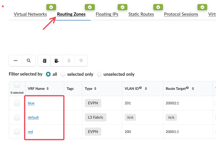
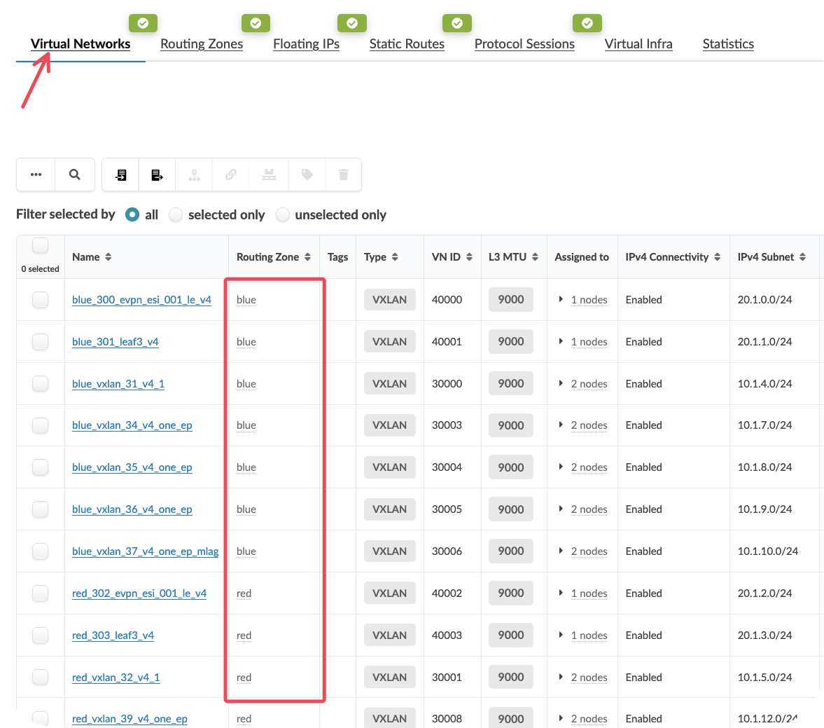
Review the Virtual Networks section to see which VXLANs exist in each VRF
Value Point: This view provides complete visibility into your logical network architecture. You can see exactly which virtual networks belong to which routing zones, and plan migrations accordingly.
Step 2: Select Virtual Networks for Migration
In the Virtual Networks section, identify the VXLANs currently in the Blue VRF that you want to migrate
Select multiple virtual networks by clicking on them (for example, select 3 VXLANs)
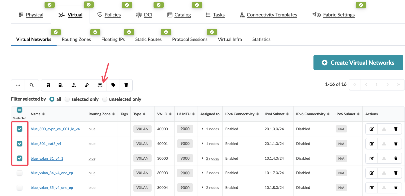
Customer Question: “How do you currently track which network segments belong to which VRFs across your entire fabric? What happens when you need to reorganise them?”
Value Point: The ability to perform bulk operations means you can migrate entire service tiers or customer segments simultaneously, rather than handling each network individually.
Step 3: Initiate the Migration
With your virtual networks selected, click Migrate Selected Virtual Networks at the top of the interface
In the migration dialog, select the destination routing zone (Red VRF)
Click Migrate to begin the process
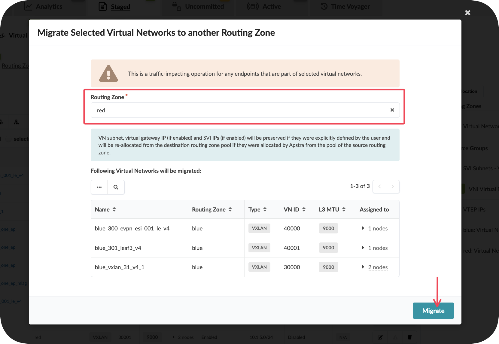
Key Insight: At this point, Apstra is calculating all the necessary configuration changes across every device in your fabric that hosts these virtual networks. This could be 30, 50, or 100+ leaf switches – all handled automatically.
Step 4: Understand What’s Happening Behind the Scenes
While the migration appears simple from the interface, Apstra is performing complex operations:
Automatic Impact Analysis: Identifying every device that requires configuration changes
Configuration Generation: Creating new VRF memberships, route targets, and EVPN configurations
Dependency Management: Ensuring all routing and forwarding tables are updated consistently
Service Preservation: Maintaining all existing connectivity while changing the underlying VRF structure
Value Point: You don’t need to think about where the impact is. All connectivity stays exactly the same – you’re simply moving logical elements from one VRF concept to another.
Step 5: Verify the Migration
After the migration completes, observe that the selected virtual networks now appear under the Red VRF
Note that all connectivity remains intact – this is a seamless architectural change
Examine the topology to confirm that no service disruption has occurred
Storytelling Tip: Emphasise that this represents complex migrations becoming simple operations instead of career-defining stress events. The fear of architectural changes transforms into confidence in network evolution.
What You’ve Accomplished
You’ve just:
Migrated multiple virtual networks between VRFs without any service disruption
Demonstrated bulk migration capabilities that scale to hundreds of devices
Shown how Apstra handles complex configuration changes automatically across the entire fabric
Illustrated architectural flexibility that enables network evolution without downtime
Business Impact: This capability enables organisations to evolve their network architecture based on changing business requirements rather than being constrained by operational complexity.
ROI Discussion Point: Consider the cost of architectural stagnation. When network changes are too complex or risky to implement, organisations accumulate technical debt that eventually constrains business growth. Apstra eliminates this constraint by making architectural evolution simple and safe.
Competitive Positioning
Apstra Advantage: Unlike solutions that require manual configuration of each device, Apstra understands the complete logical-to-physical mapping. This system-level intelligence enables complex migrations to be expressed as simple intent changes.
Discovery Questions for Further Conversation:
“Are you confident making changes in your production DCs?”
“What prevents you from making architectural improvements to your current network?”
“How much planning time would a VRF migration require in your environment?”
“What’s your current process for ensuring zero downtime during network changes?”
Business Value Summary
Speed and Simplicity: What traditionally took weeks now takes minutes Risk Reduction: Complex migrations become predictable, tested operations Business Agility: Network architecture can evolve with business requirements Operational Confidence: Engineers can make architectural improvements without fear
Customer Story Integration: “A few clicks and we could move entire sets of L2 segments to a new VRF,” the customer explained with amazement. “What we thought would be weeks of careful migration work became an afternoon task. The logical network architecture we’d been putting off suddenly became achievable without the operational nightmare we’d feared.”
Next Steps
With physical expansion, virtual network creation, and architectural migration capabilities demonstrated, your customers can see how Apstra enables complete network lifecycle management. The combination of these capabilities transforms network operations from a constraint into a competitive advantage.
Storytelling Tip: Position this demonstration within the broader context of business agility. The ability to rapidly provision network services and evolve architecture directly enables faster time-to-market and the ability to capture new revenue opportunities that might otherwise be lost to competitors.
Day 2 Operations & Assurance
Overview
Traditional network monitoring requires teams to correlate data from multiple systems to understand overall fabric health. Apstra’s main dashboard provides a unified view of your entire data centre fabric, presenting only the information that matters for operational decisions. This eliminates the noise typical of monitoring systems whilst ensuring critical issues receive immediate attention.
Objectives
By completing this section, you will demonstrate:
How Apstra presents fabric-wide health status from a single interface
The difference between reactive monitoring and intent-based validation
Real-time visibility into actual network traffic and performance
How contextual monitoring reduces false alerts and operational overhead
Lab environment note
This blueprint provides read-only access to a live Apstra environment with real network traffic. You should expect to see active telemetry data and various alerts or anomalies that demonstrate Apstra’s monitoring capabilities. However, the specific data and alerts visible will depend on current network activity and may vary between demonstration sessions.
Context within the overall guide
The main dashboard represents the culmination of intent-based networking in action. All the configuration, automation and documentation capabilities we’ve demonstrated now provide the foundation for intelligent monitoring that understands what your network should be doing and alerts only when it deviates from that intent.
Business context
Network operations teams typically spend significant time triaging false alerts and correlating data across multiple monitoring tools. Studies show that 70% of network alerts are false positives, leading to alert fatigue and missed critical issues. Apstra’s intent-aware monitoring presents only genuine deviations from expected behaviour, dramatically improving operational efficiency whilst reducing the risk of missing real problems.
Demonstration steps
Step 1: Access the live traffic environment
Open a new browser tab and navigate to:
https://10.28.173.3Log in using the credentials:
Username:
se_demoPassword:
se_demo
Select the appropriate blueprint from the available options
Ensure you’re viewing either of the blueprints
Value point: This environment contains real network traffic flowing through an actual Apstra-managed fabric. Unlike static demonstrations, this shows how Apstra monitors live production-style workloads with genuine telemetry data.
Customer question: “How confident are you that your current monitoring system would immediately alert you to subtle performance degradations or configuration deviations?”
Storytelling tip: Emphasise that customers will see real network behaviour, not simulated data. This demonstrates Apstra’s ability to handle actual production scenarios.
Step 3: Examine fabric health indicators
Review the overall fabric status indicators at the top of the dashboard
Observe any active alerts or anomalies currently detected
Click on individual status indicators to understand their significance
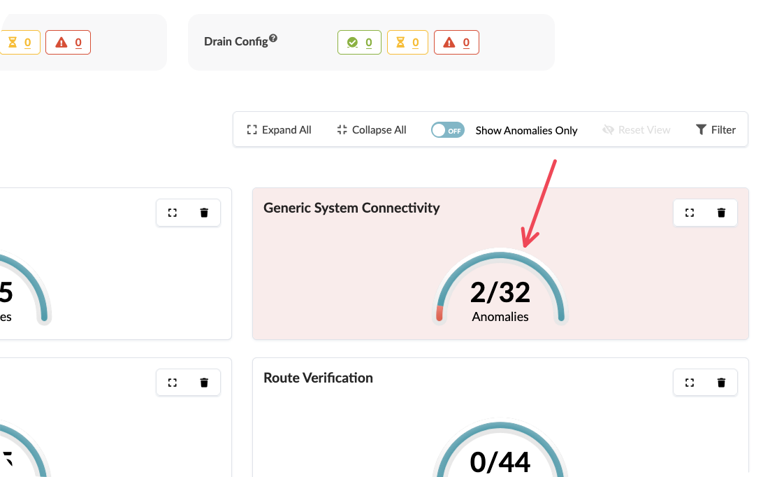
Value point: Apstra distinguishes between expected network behaviour and genuine issues. The system understands your design intent, so it only presents alerts for actual deviations rather than normal operational changes.
Storytelling tip: Contrast this with traditional monitoring where teams receive alerts for routine events like BGP session flaps during maintenance windows or normal traffic fluctuations.
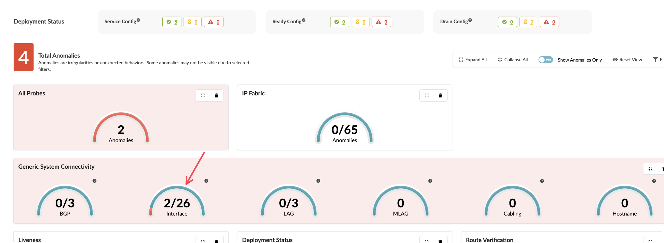
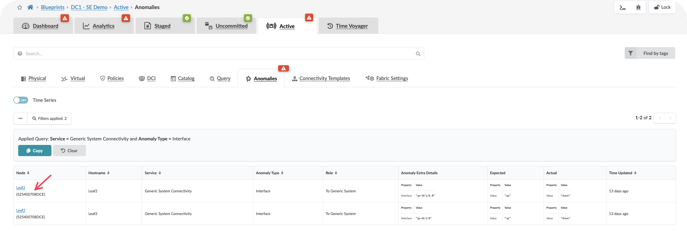
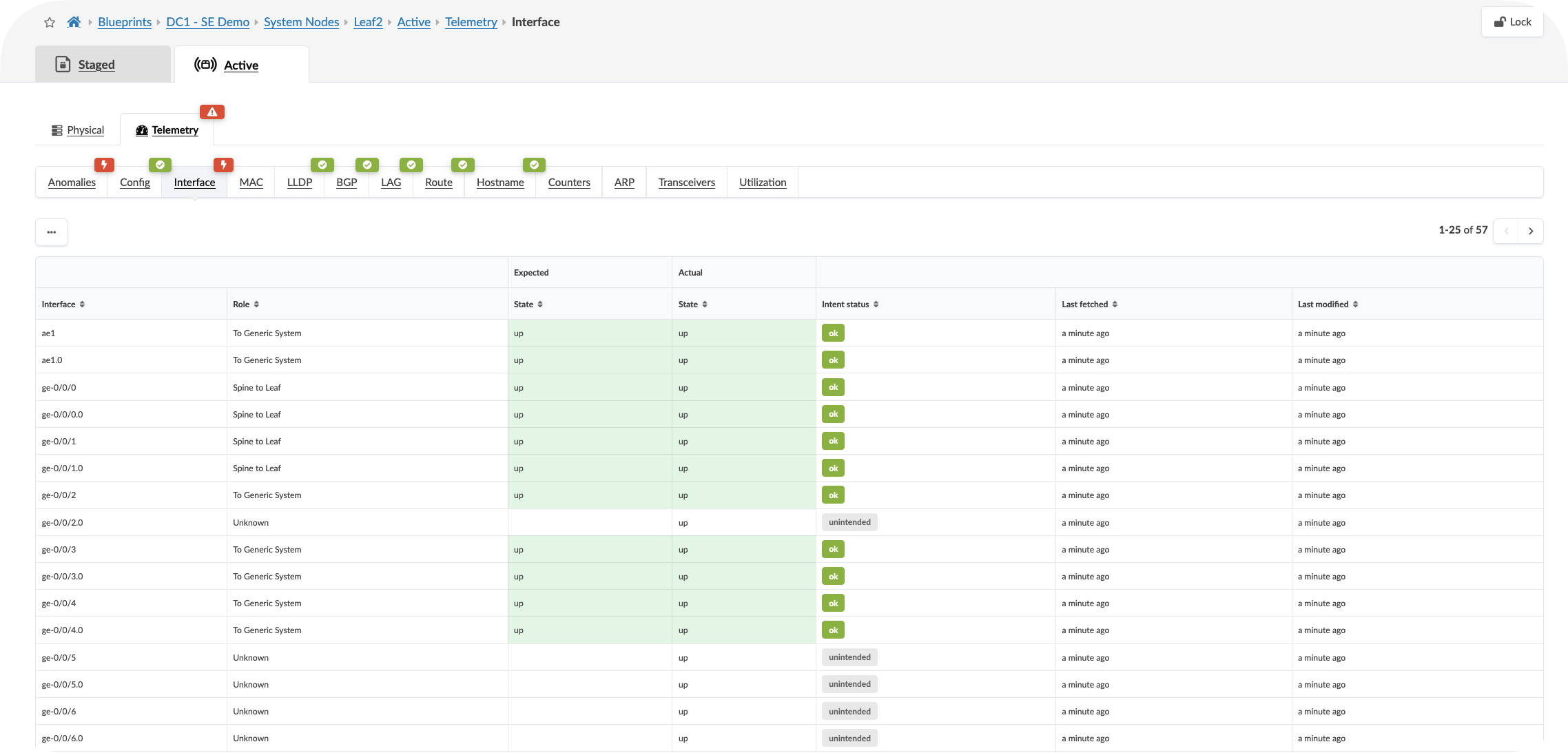
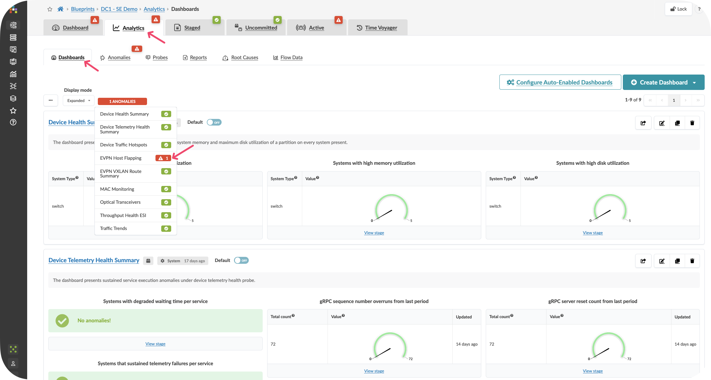
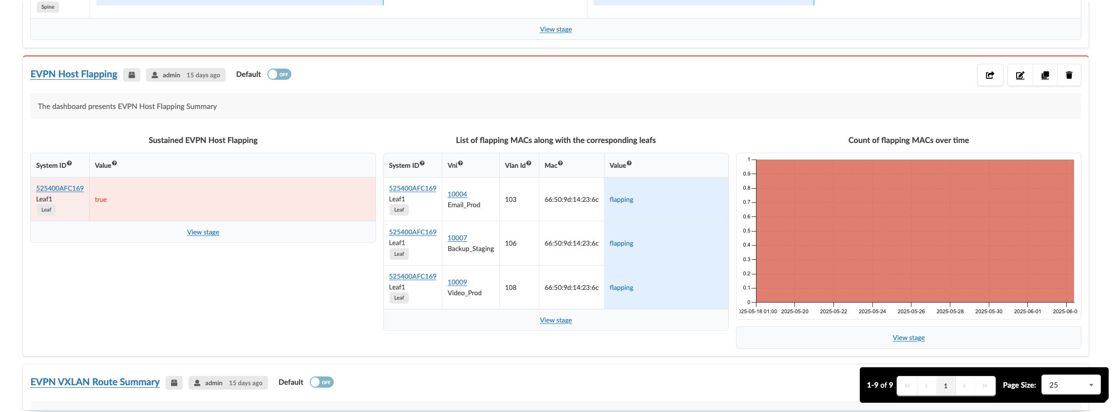
Step 4: Explore Analytics
Locate the Analytics Tab and view the dashboard
Click onbe the highlighted dashboard widgets showing anaomalies if present
CLick On the Anomalies tab to see the raw anomaly alerts activated by probes. You can dive into information about the affected components by selecting the stage.
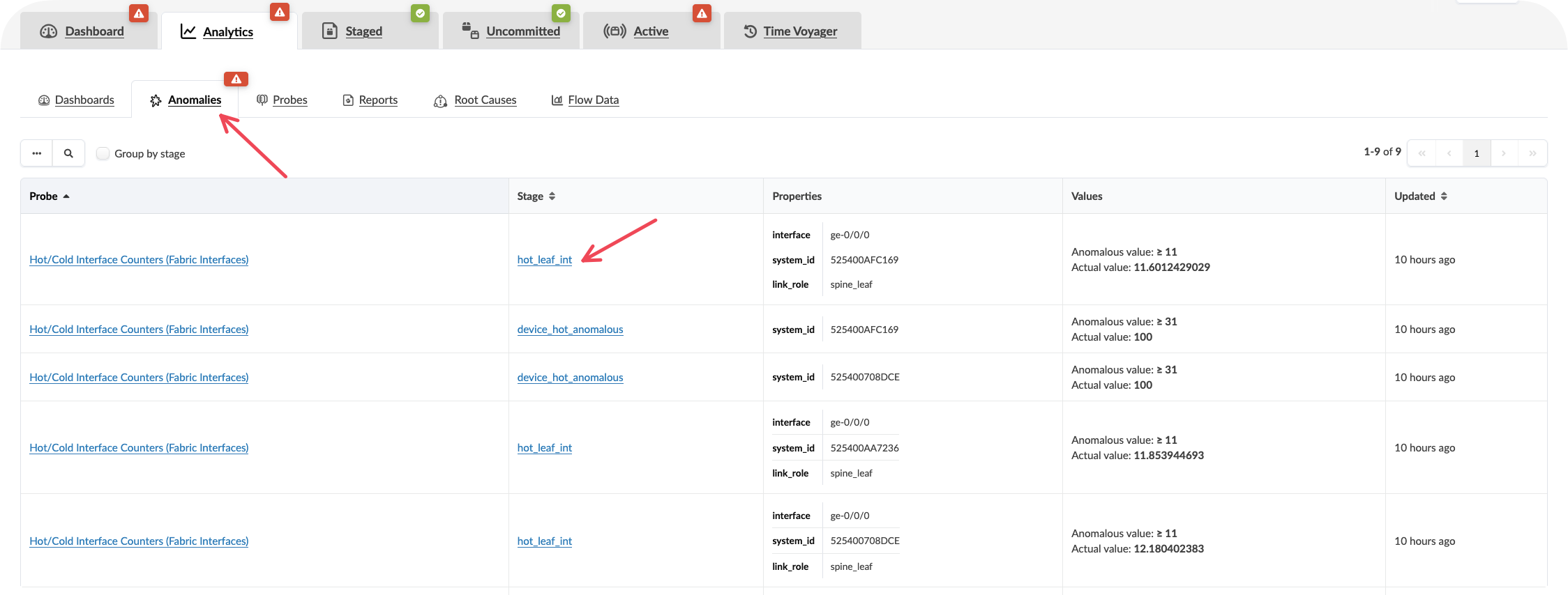
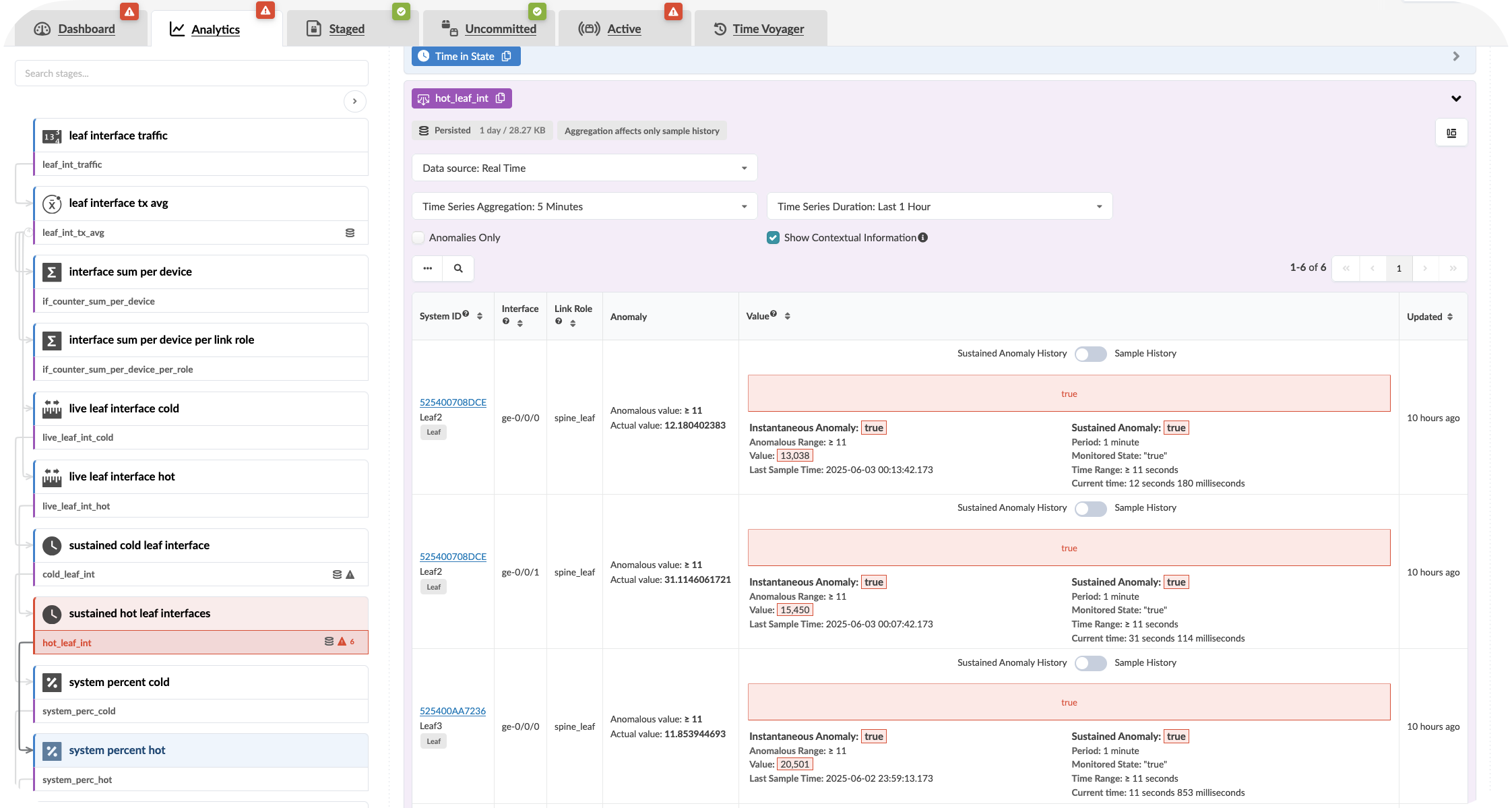
Value point: Each alert includes the context of what should be happening versus what is actually occurring. This eliminates the time typically spent investigating whether an alert represents a real issue or expected behaviour.
Customer question: “When your monitoring system generates an alert, how long does it typically take your team to determine whether it requires immediate action or can be safely ignored?”
Step 5: Review fabric capacity indicators
Locate capacity utilisation metrics on the dashboard
Examine bandwidth utilisation across fabric links
Review any capacity planning indicators or trending information
Observe how the information is presented at both fabric-wide and component levels
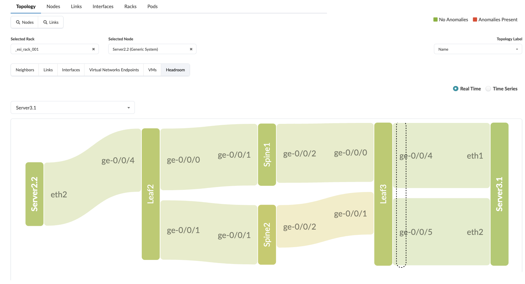
Showing the Fabric Heatmap:
Go to Active >> Select a Server
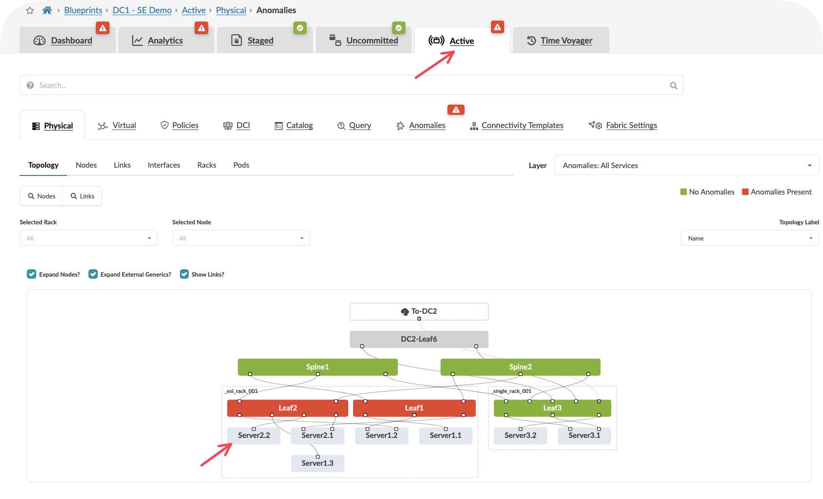
Select Headroom
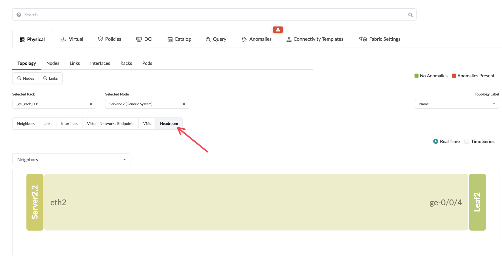
Select a Neighbouring Server
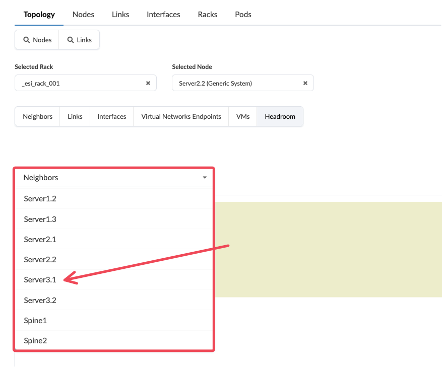
You can now view the entire path through the network and the utilisation of the swiches and links by hovering over them
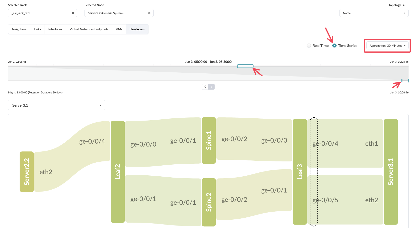
You can also select
time seriesand view the path at different times over the last 30 days.
Value point: Fabric capacity monitoring happens automatically across all components without requiring manual configuration of individual device thresholds. As you add or remove network elements, capacity monitoring adjusts automatically.
Customer question: “How do you currently track whether your network fabric has sufficient capacity for planned growth or unexpected traffic spikes?”
Key benefits demonstrated
Operational efficiency: Single interface provides complete fabric visibility without requiring correlation across multiple monitoring tools.
Intelligent alerting: Intent-based monitoring eliminates false positives by understanding what constitutes normal versus abnormal behaviour for your specific network design.
Proactive capacity management: Automatic capacity tracking across the entire fabric enables informed decisions about network expansion before issues arise.
Reduced mean time to resolution: Contextual alerts provide immediate insight into problem scope and potential solutions.
Advanced considerations
Customisation capabilities: The main dashboard can be tailored to highlight the metrics most relevant to your operational priorities whilst maintaining the clean, actionable interface.
Integration potential: Dashboard data can feed into broader operational workflows and external systems through Apstra’s APIs, enabling automated response capabilities.
Historical analysis: Long-term trending data supports capacity planning and helps identify patterns that might indicate emerging issues before they affect service.
Conclusion and key takeaways
Apstra’s main dashboard transforms network monitoring from a reactive, correlation-heavy process into a proactive, intent-aware system. By understanding your network’s design purpose, the system presents only actionable information whilst eliminating the noise that typically overwhelms operations teams. This approach not only improves response times for genuine issues but also enables network engineers to focus on strategic improvements rather than constant alert triage.
The real-time traffic flowing through this demonstration environment proves that intent-based monitoring works effectively in actual production scenarios, providing the confidence needed to rely on Apstra for mission-critical network operations.
Lab conclusion
Throughout this demonstration, we’ve walked through the fundamental Apstra workflow that organisations experience when deploying and managing their data centre infrastructure. We began with the initial deployment process, establishing the fabric design and bringing devices online with minimal manual intervention. From there, we expanded the network capacity to meet growing business demands, demonstrating how Apstra accommodates change without the traditional complexity and risk associated with network modifications.
The Day Two operations we explored – from monitoring network health to troubleshooting connectivity issues – showcase how Apstra transforms ongoing network management from a reactive, time-intensive process into a proactive, streamlined operation. The platform’s ability to provide continuous validation and real-time insights fundamentally changes how network teams operate, shifting their focus from firefighting to strategic network optimisation.
These demonstrations represent just a glimpse of what’s possible with Apstra. Every customer environment presents unique challenges, requirements, and opportunities. The scenarios we’ve covered align with the core use cases discussed in our demonstration presentations, but they barely scratch the surface of the platform’s capabilities.
The reality is that demonstrating a platform like Apstra effectively requires understanding your specific customer’s pain points and tailoring the demonstration accordingly. A financial services organisation worried about compliance and audit trails will need to see different capabilities than a cloud service provider focused on rapid service deployment. This is why developing familiarity with the platform becomes essential – you need the confidence to navigate Apstra’s features dynamically, responding to customer questions and interests as they arise during your conversation.
Practice remains the foundation of effective demonstrations. The more time you spend exploring different scenarios and understanding how various features interconnect, the better equipped you’ll be to address unexpected customer questions or pivot the demonstration based on their reactions. Each interaction with the platform builds your confidence and deepens your understanding of how to position its value effectively.
We recognise that mastering all aspects of Apstra takes time, and you’re not expected to become an expert overnight. The Apstra TME team stands ready to support your learning journey and help you prepare for specific customer engagements. Whether you need clarification on technical concepts, assistance with demonstration scenarios, or guidance on positioning strategies, the team at apstra-pse@juniper.net is here to help.
Your customer interactions also provide valuable insights that help shape our demonstration approaches. If you discover new scenarios that resonate particularly well with prospects, or if you encounter customer questions that we haven’t addressed in these materials, please share those experiences with the team. Understanding what captures customer attention and drives meaningful conversations helps us refine our demonstration strategies and develop additional scenarios that support your success.
The most effective Apstra demonstrations happen when you can confidently guide customers through scenarios that directly address their specific challenges. This foundation gives you the platform knowledge to make those demonstrations compelling and relevant, but your ongoing practice and customer feedback will make them truly powerful.
Lab Survey
Please take 2 minutes and complet the Apstra Demonstration Hands-On Lab Survey