SRv6 and MPLS Core and Edge Link Slicing
Overview
Segment Routing (both SR-MPLS and SRv6) is becoming increasing traction among network operators. It is a technology, that promises simplicity (by eliminating label distribution protocols, and keeping everything within routing protocol), and better functionality (no states in the network for traffic engineering, topology independent LFA, flex-algo for lightweight network partitioning, etc.).
One of the aspects of segment routing is network slicing. Both, SR-MPLS as well as SRv6, provides architectural framework to implement partitions – or slices – in the network. With each partition/slice having dedicated resources – capacity, queues, buffers – on transmission links. Transport network slicing opens doors for new uses cases, like for example network sharing (where multiple entities share the network, while keeping dedicated resources in the network) or network slice services (where services with SLA can be established).
This lab discusses the guaranteed link slicing feature, using MPLS and SRv6 as underlay transport.
Link slicing is a specific use case under overall umbrella called “network slicing”. With link slicing, you slice (channelize, partition, divide, etc. – use the word you like) a single link in such a way, that each slice has explicit capacity guarantee, and each slice can have multiple traffic classes and queues.
This lab is based on the capabilities of Junos 23.4R2 (or newer Junos release) running on MX Series routers. Configuration and operational command outputs have been collected on vMX.
Objectives
Participants will learn how to enable, configure and troubleshoot link slicing, both in SR-MPLS as well as in SRv6 environment.
Key Topics
Link slicing overview
Implementation of link slicing with slice-aware H-QoS
Slice-aware H-QoS configuration
Assignment of traffic to slices – MPLS
Assigning of traffic to slices – SRv6
Skills and Tools
Prerequisites: Basic understanding of IS-IS, BGP and L3VPN concepts, as well as SR-MPLS and SRv6 concepts. Additionally, understanding of Junos H-QoS framework
Tools Used: Junos CLI, Ixia traffic tester
Methodology
Acting as a member of a network operations team, participants will engage in configuring, provisioning, monitoring and troubleshooting of link slicing, both with SR-MPLS and SRv6 transport underlays. Trough guided exercises, you will follow step-by-step process to implement link slicing in an example network – both for SR-MPLS and SRv6.
Benefits
Gain valuable skills in deploying link slicing in the network – both from the design and concept perspective, as well as from configuration and troubleshooting perspective. Participants will walk away with understanding link slicing methodology and traffic mapping to slices.
Lab Topology and Architecture
Lab Blueprint Topology
Transport Infrastructure (P/PE)
Router-ID: 198.51.100.
Loopback: 2001:db8:bad:cafe:
00:: /128 SRv6 locator: fc01:
: ::/48 Core Links: 2001:db8:beef:
00:: : /112
PE-CE links:
IPv4:
. . . /24 IPv6: 2001:db8:babe:face:
:: : /112
VPN (Virtual Private Network) Loopbacks (CE/PE):
192.168.
. /32 2001:db8:abba:
:: /128
The lab is preconfigured with following items:
IP addresses
IS-IS with SR-MPLS and SRv6 extensions (with corresponding policies)
BGP (with corresponding policies)
Basic QoS (on PE11 and PE21 only)
L3VPN instances (on PE11 and PE21 only)
Name |
Type |
|---|---|
RI-VRF15 |
SRv6 |
RI-VRF16 |
SRv6 |
RI-VRF17 |
SR-MPLS |
RI-VRF25 |
SRv6 |
RI-VRF26 |
SRv6 |
RI-VRF27 |
SR-MPLS |
RI-VRF35 |
SRv6 |
RI-VRF36 |
SRv6 |
RI-VRF37 |
SR-MPLS |
In this lab users will perform following actions:
configure slice-aware H-QoS (on P1 and P2 routers only)
configure firewall filter based slice selection (on P1 and P2 routers only)
modify VRF configurations to include deterministic slice identifier (on PE11 and PE21 routers only)
preform verification at multiple steps
Access details
Each lab is prepared for two users:
User 1: deals with traffic direction CE91 -> CE92, and configures only PE21 and P1 routers
User 2: deals with traffic direction CE92 -> CE91, and configures only PE11 and P2 routers
Each user can perform their tasks individually without reliance on the other
Open a browser from your Laptop and http into server IP that you recieved throug mail, and use the credentials present in the same mail to login to the server. Once logged in, you will see the routers assigned to you, click on it to get to the router CLI.
User 1 will see the below routers after logging in to the server
Device |
|---|
P1 |
PE21 |
User 2 will see the below routers after logging in to the server
Device |
|---|
P2 |
PE11 |
There is no dependenacy
Architecture Introduction
The network topology and initial configuration used for this lab is outlined in Figure 1. We have multi-domain network architecture with VRFs placed on the PE routers, and L3VPN over SRv6 Inter-AS Option-C framework to provide L3VPN connectivity between VRFs on the PEs in different domains. In addition to SRv6 Inter-AS Option-C, SR-MPLS Inter-AS Option-C has been added, so that link slicing for both MPLS and SRv6 underlays can be demonstrated.
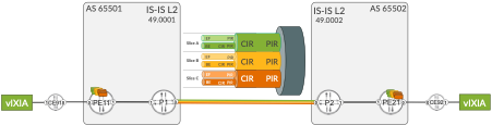
PE routers have multiple L3VPNs. Some of these VPNs use SRv6 as underlay, and some of these VPNs use SR-MPLS as underlay. Thus, in this lab both underlay types (SR-MPLS and SRv6) are used concurrently.
This is a realistic scenario and might occur, for example, during migration procedure to migrate from MPLS to SRv6 underlay.
Nevertheless, focus of this lab is not the discussion about nuances of concurrent running of SR-MPLS or SRv6 underlays. Focus of this lab is link slicing, and both underlays are simply used to illustrate that link slicing can work with both MPLS (any type of MPLS, not only SR-MPLS) and SRv6.
Link Slicing Introduction
Before going into configuration or operational commands details, let’s discuss the use case: what is a “link slicing”, where and how we could use link slicing?
Link slicing is a specific use case under overall umbrella called “network slicing”. With link slicing, you slice (channelize, partition, divide, … – use the word you like) a single link is such a way, that each slice has explicit capacity guarantee, and each slice can have multiple traffic classes and queues. For example, Flexible Ethernet (FlexE) is a technology that allows to channelize an Ethernet link, with fixed bandwidth guarantees for each channel.
Saying that, FlexE might not be the best technology for link slicing/channelization. The major drawbacks of FlexE, when used for link slicing/channelization are:
no statistical multiplex gain/no bandwidth reuse between channels
requires large physical links (50 Gbps and above) with large b/w increments (5 Gbps)
requires an underlying electrical transport switching layer to support channelization
Therefore, to overcome the drawbacks associated with FlexE, this lab uses different approach for link slicing, utilizing hierarchical QoS (H-QoS) toolset. Traditional, legacy H-QoS architecture is depicted in Figure 2.
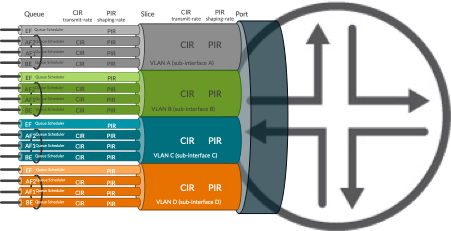
In the traditional architecture the link is divided into subinterfaces (units in Junos terms), where each subinterface is associated with a VLAN. The QoS profile (traffic control profile in Junos terms) contains QoS parameters for each subinterface, like:
CIR (Committed Information Rate) – guaranteed minimum rate
PIR (Peak Information Rate) – maximum (shaping) rate
Queue parameters inside each profile, with queue priorities, queue sizes, minimum/maximum rate of each queue, etc.
We could reuse this model for link slicing – theoretically at least. So, why we don’t do it? What is the problem with this model?
Well, if you look at Figure 1, the depicted use case for link slicing is to slice inter-AS link (please note, this is just an example; there could be many other use cases calling for link slicing at different locations in the network). With traditional H-QoS approach for link slicing, it would mean considerable administrative overhead:
VLAN allocation and co-ordination between two domains
IP addressing for each subinterface allocation and co-ordination between two domains
In case of intra-domain link slicing, multiple IGP adjacencies would need to be started to make the subinterfaces usable for traffic
In case of inter-domain link slicing, multiple eBGP peerings, and/or import/export BGP policies with next-hop manipulation to make the subinterfaces usable for traffic
This might become complex task, especially, if the use case demands slicing on multiple links.
Link Slicing with slice-aware H-QoS
To address this complexity, starting from Junos 22.2 Juniper successively began to introduce features allowing H-QoS deployments for link slicing in much simpler manner (slice-aware H-QoS). This lab uses features available from Junos 23.4.
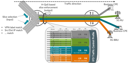
In essence, slice-aware H-QoS uses abstract objects called ‘slices’ to attach QoS profiles on the link. So, no subinterfaces, VLANs, multiple IP addresses, multiple IGP/BGP sessions on the link are longer required, as with traditional H-QoS model. This simplifies operations and does not affect packet forwarding in any way.
When packets enter the router, they are classified as belonging to a specific slice. Packets not classified explicitly, are associated with a default slice. Packet classification, implemented with firewall filter, can happen practically based on any existing field in the packet, like for example top MPLS label, bottom MPLS label, Src/Dst IP address, some specific bits from Src/Dst IP address, etc.
When the packet leaves the router on sliced link, packets are subject to the treatment defined in the slice-specific QoS profile, based on the slice selection performed on input.
Slice-aware H-QoS Configuration
In the topology depicted in Figure 1, link slicing will be configured on inter-AS links. Configuration of P1 router will be discussed.
First, the slices must be initialized, as outlined in Configuration 1. As an example, we will be using 3 slices, called NS-A, NS-B and NS-C, to illustrate link slicing capability.
Starting the Lab
If you want to Copy and Paste the Configurations in CLI, do Ctrl + Option/Alt + Shift which will open guacamole built-in Clipboard. then Paste the commands in clipboard, after that do Ctrl+Option/Alt+Shift again to close the clipboard, then right click on CLI to paste the configs.
STEP-1 (P1/P2 Router)
Configuration |
|---|
set services network-slicing slice NS-A |
set services network-slicing slice NS-B |
set services network-slicing slice NS-C |
 1	services {
 2		network-slicing {
 3			slice NS-A;
 4			slice NS-B;
 5			slice NS-C;
 6		}
 7	}
Second, hierarchical scheduler capability on the sliced interface must be enabled, as outlined in Configuration 2. Please note, in older Junos releases enabling hierarchical scheduler is possible only on interface divided into subinterfaces (VLANs), to support classical H-QoS. Junos 23.4 removes that restriction, allowing enabling hierarchical scheduler capability on plain (not divided to subinterfaces) interfaces as well, for slice-aware H-QoS support.
STEP-2 (P1/P2 Router)
Configuration |
|---|
set interfaces ge-0/0/0 hierarchical-scheduler |
1	interfaces {
2		ge-0/0/0 {
3			hierarchical-scheduler;
4		}
5	}
Now, QoS configuration must be prepared, with QoS profiles attached to the slices on the interface. This lab does not intent to cover Junos QoS in details, as this is quite huge topic. Therefore, to demonstrate slicing capability, relatively simple QoS configuration is used, as outlined in Configuration 3:
STEP-3 (P1/P2 Router)
Configuration |
|---|
set class-of-service classifiers dscp CL-DSCP forwarding-class FC-BE loss-priority low code-points be |
set class-of-service classifiers dscp CL-DSCP forwarding-class FC-EF loss-priority low code-points ef |
set class-of-service classifiers dscp-ipv6 CL-DSCP forwarding-class FC-BE loss-priority low code-points be |
set class-of-service classifiers dscp-ipv6 CL-DSCP forwarding-class FC-EF loss-priority low code-points ef |
set class-of-service classifiers exp CL-MPLS forwarding-class FC-BE loss-priority low code-points 000 |
set class-of-service classifiers exp CL-MPLS forwarding-class FC-EF loss-priority low code-points 101 |
set class-of-service forwarding-classes class FC-BE queue-num 0 |
set class-of-service forwarding-classes class FC-BE priority low |
set class-of-service forwarding-classes class FC-EF queue-num 1 |
set class-of-service forwarding-classes class FC-EF priority high |
set class-of-service traffic-control-profiles TC-1G shaping-rate 1g |
set class-of-service traffic-control-profiles TC-NS-A scheduler-map SM-NS-A |
set class-of-service traffic-control-profiles TC-NS-A shaping-rate 100m |
set class-of-service traffic-control-profiles TC-NS-A guaranteed-rate 50m |
set class-of-service traffic-control-profiles TC-NS-B scheduler-map SM-NS-B |
set class-of-service traffic-control-profiles TC-NS-B shaping-rate 5600000 |
set class-of-service traffic-control-profiles TC-NS-B guaranteed-rate 5m |
set class-of-service traffic-control-profiles TC-NS-C scheduler-map SM-NS-C |
set class-of-service traffic-control-profiles TC-NS-C shaping-rate 5100000 |
set class-of-service traffic-control-profiles TC-NS-C guaranteed-rate 4m |
set class-of-service interfaces ge-* unit * classifiers dscp CL-DSCP |
set class-of-service interfaces ge-* unit * classifiers dscp-ipv6 CL-DSCP |
set class-of-service interfaces ge-* unit * classifiers exp CL-MPLS |
set class-of-service interfaces ge-0/0/0 output-traffic-control-profile TC-1G |
set class-of-service interfaces ge-0/0/0 slice NS-A output-traffic-control-profile TC-NS-A |
set class-of-service interfaces ge-0/0/0 slice NS-B output-traffic-control-profile TC-NS-B |
set class-of-service interfaces ge-0/0/0 slice NS-C output-traffic-control-profile TC-NS-C |
set class-of-service scheduler-maps SM-NS-A forwarding-class FC-BE scheduler SC-BE |
set class-of-service scheduler-maps SM-NS-A forwarding-class FC-EF scheduler SC-EF |
set class-of-service scheduler-maps SM-NS-B forwarding-class FC-BE scheduler SC-BE |
set class-of-service scheduler-maps SM-NS-B forwarding-class FC-EF scheduler SC-EF |
set class-of-service scheduler-maps SM-NS-C forwarding-class FC-BE scheduler SC-BE |
set class-of-service scheduler-maps SM-NS-C forwarding-class FC-EF scheduler SC-EF |
set class-of-service schedulers SC-BE transmit-rate remainder |
set class-of-service schedulers SC-BE priority low |
set class-of-service schedulers SC-EF transmit-rate percent 50 |
set class-of-service schedulers SC-EF transmit-rate rate-limit |
set class-of-service schedulers SC-EF priority strict-high |
 1	class-of-service {
 2	    classifiers {
 3	        dscp CL-DSCP {
 4	            forwarding-class FC-BE {
 5	                loss-priority low code-points be;
 6	            }
 7	            forwarding-class FC-EF {
 8	                loss-priority low code-points ef;
 9	            }
 10	        }
 11	        dscp-ipv6 CL-DSCP {
 12	            forwarding-class FC-BE {
 13	                loss-priority low code-points be;
 14	            }
 15	            forwarding-class FC-EF {
 16	                loss-priority low code-points ef;
 17	            }
 18	        }
 19	        exp CL-MPLS {
 20	            forwarding-class FC-BE {
 21	                loss-priority low code-points 000;
 22	            }
 23	            forwarding-class FC-EF {
 24	                loss-priority low code-points 101;
 25	            }
 26	        }
 27	    }
 28	    forwarding-classes {
 29	        class FC-BE queue-num 0 priority low;
 30	        class FC-EF queue-num 1 priority high;
 31	    }
 32	    traffic-control-profiles {
 33	        TC-1G {
 34	            shaping-rate 1g;
 35	        }
 36	        TC-NS-A {
 37	            scheduler-map SM-NS-A;
 38	            shaping-rate 100m;
 39	            guaranteed-rate 50m;
 40	        }
 41	        TC-NS-B {
 42	            scheduler-map SM-NS-B;
 43	            shaping-rate 5600000;
 44	            guaranteed-rate 5m;
 45	        }
 46	        TC-NS-C {
 47	            scheduler-map SM-NS-C;
 48	            shaping-rate 5100000;
 49	            guaranteed-rate 4m;
 50	        }
 51	    }
 52	    interfaces {
 53	        ge-* {
 54	            unit * {
 55	                classifiers {
 56	                    dscp CL-DSCP;
 57	                    dscp-ipv6 CL-DSCP;
 58	                    exp CL-MPLS;
 59	                }
 60	            }
 61	        }
 62	        ge-0/0/0 {
 63	            output-traffic-control-profile TC-1G;
 64	            slice NS-A {
 65	                output-traffic-control-profile TC-NS-A;
 66	            }
 67	            slice NS-B {
 68	                output-traffic-control-profile TC-NS-B;
 69	            }
 70	            slice NS-C {
 71	                output-traffic-control-profile TC-NS-C;
 72	            }
 73	        }
 74	    }
 75	    scheduler-maps {
 76	        SM-NS-A {
 77	            forwarding-class FC-BE scheduler SC-BE;
 78	            forwarding-class FC-EF scheduler SC-EF;
 79	        }
 80	        SM-NS-B {
 81	            forwarding-class FC-BE scheduler SC-BE;
 82	            forwarding-class FC-EF scheduler SC-EF;
 83	        }
 84	        SM-NS-C {
 85	            forwarding-class FC-BE scheduler SC-BE;
 86	            forwarding-class FC-EF scheduler SC-EF;
 87	        }
 88	    }
 89	    schedulers {
 90	        SC-BE {
 91	            transmit-rate {
 92	                remainder;
 93	            }
 94	            priority low;
 95	        }
 96	        SC-EF {
 97	            transmit-rate {
 98	                percent 50;
 99	                rate-limit;
 100	            }
 101	            priority strict-high;
 102	        }
 103	    }
 104	}
The main aspects of this sample QoS configuration are as follows:
Two forwarding classes – FC-BE and FC-EF – (lines 28-31). Please note, this is only example. Each slice can support up to 8 forwarding classes.
DSCP and MPLS TC classifiers to classify packets into the forwarding class based on DSCP or MPLS TC values in the packet (lines 2-27). Additionally, classifiers are assigned to the interfaces (lines 53-61).
Traffic control profiles – per port and per slice profiles – (lines 32-51). Per slice profiles have some example minimum (guaranteed) rates and maximum (shaping) rates. Additionally, traffic control profiles is attached to the sliced interface (lines 62-73), resulting in H-QoS hierarchy depicted in Figure 1.
Traffic control profiles reference scheduler maps (lines 37, 42, 47, 75-88), which define queue parameters for each slice via schedulers (lines 89-103). In this simple example, each slice uses the same queue parameters for simplification. However, in the production deployment, each slice can be parametrized differently, based on the actual requirements.
As the result of the QoS configuration, we have three slices as follows:
Slice name |
min BW |
max BW |
Queues |
|---|---|---|---|
NS-A |
50 Mbps |
100 Mbps |
FC-EF: strict-high, 50% (rate limited) / FC-BE: low, remaining slice BW |
NS-B |
5 Mbps |
5.6 Mbps |
FC-EF: strict-high, 50% (rate limited) / FC-BE: low, remaining slice BW |
NS-C |
4 Mbps |
5.1 Mbps |
FC-EF: strict-high, 50% (rate limited) / FC-BE: low, remaining slice BW |
Based on the configuration done so far, initial checks can be performed.
STEP-4 (P1/P2 router - required on vMX)
 1	kszarkowicz@P1> show interfaces queue ge-0/0/0 slice NS-A
 2	error: Get slice-id from slice-name:NS-A on ge-0/0/0 failed. Error: No such file or directory.
 3
 4
 5	kszarkowicz@P1> show interfaces queue ge-0/0/0 slice NS-A
 6	error: slice 'NS-A' not found on ge-0/0/0. Abort
Depending on the MX hardware used, it might happen – especially on older MX line cards, or on virtual MX – that configuration discussed so far is not sufficient to enable slice-aware H-QoS. Therefore, in this lab, which is based on vMX, this additional configuration must be performed (Configuration 4).
STEP-5 (P1/P2 Router - required on vMX)
Configuration |
|---|
set chassis fpc 0 pic 0 traffic-manager mode egress-only |
set chassis fpc 0 flexible-queuing-mode |
 1	chassis {
 2	    fpc 0 {
 3	        pic 0 {
 4	            traffic-manager {
 5	                mode egress-only;
 6	            }
 7	        }
 8	        flexible-queuing-mode;
 9	    }
 10	}
Wait 10-15 seconds for FPC reprogramming. After that, finally, initial checks can be performed (CLI-Output 2). Please note, based on the MX line card used, the output of the operational command might be slightly different.
STEP-6 (P1/P2 Router)
 1	kszarkowicz@P1> show interfaces queue ge-0/0/0 slice NS-A
 2	Slice : NS-A (Index : 1)
 3	  Anchor interface : ge-0/0/0 (Index : 152)
 4	Forwarding classes: 16 supported, 4 in use
 5	Egress queues: 8 supported, 4 in use
 6	Queue: 0, Forwarding classes: FC-BE
 7	  Queued:
 8	    Packets              :                     0                     0 pps
 9	    Bytes                :                     0                     0 bps
 10	  Transmitted:
 11	    Packets              :                     0                     0 pps
 12	    Bytes                :                     0                     0 bps
 13	    Tail-dropped packets :                     0                     0 pps
 14	    RL-dropped packets   :                     0                     0 pps
 15	    RL-dropped bytes     :                     0                     0 bps
 16	    RED-dropped packets  :                     0                     0 pps
 17	     Low                 :                     0                     0 pps
 18	     Medium-low          :                     0                     0 pps
 19	     Medium-high         :                     0                     0 pps
 20	     High                :                     0                     0 pps
 21	    RED-dropped bytes    :                     0                     0 bps
 22	     Low                 :                     0                     0 bps
 23	     Medium-low          :                     0                     0 bps
 24	     Medium-high         :                     0                     0 bps
 25	     High                :                     0                     0 bps
 26	  Queue-depth bytes      :
 27	    Average              :                     0
 28	    Current              :                     0
 29	    Peak                 :                     0
 30	    Maximum              :               1564672
 31	Queue: 1, Forwarding classes: FC-EF
 32	  Queued:
 33	    Packets              :                     0                     0 pps
 34	    Bytes                :                     0                     0 bps
 35	  Transmitted:
 36	    Packets              :                     0                     0 pps
 37	    Bytes                :                     0                     0 bps
 38	    Tail-dropped packets :                     0                     0 pps
 39	    RL-dropped packets   :                     0                     0 pps
 40	    RL-dropped bytes     :                     0                     0 bps
 41	    RED-dropped packets  :                     0                     0 pps
 42	     Low                 :                     0                     0 pps
 43	     Medium-low          :                     0                     0 pps
 44	     Medium-high         :                     0                     0 pps
 45	     High                :                     0                     0 pps
 46	    RED-dropped bytes    :                     0                     0 bps
 47	     Low                 :                     0                     0 bps
 48	     Medium-low          :                     0                     0 bps
 49	     Medium-high         :                     0                     0 bps
 50	     High                :                     0                     0 bps
 51	  Queue-depth bytes      :
 52	    Average              :                     0
 53	    Current              :                     0
 54	    Peak                 :                     0
 55	    Maximum              :               1564672
 56	Queue: 2, Forwarding classes: assured-forwarding
 57	  Queued:
 58	    Packets              :                     0                     0 pps
 59	    Bytes                :                     0                     0 bps
 60	  Transmitted:
 61	    Packets              :                     0                     0 pps
 62	    Bytes                :                     0                     0 bps
 63	    Tail-dropped packets :                     0                     0 pps
 64	    RL-dropped packets   :                     0                     0 pps
 65	    RL-dropped bytes     :                     0                     0 bps
 66	    RED-dropped packets  :                     0                     0 pps
 67	     Low                 :                     0                     0 pps
 68	     Medium-low          :                     0                     0 pps
 69	     Medium-high         :                     0                     0 pps
 70	     High                :                     0                     0 pps
 71	    RED-dropped bytes    :                     0                     0 bps
 72	     Low                 :                     0                     0 bps
 73	     Medium-low          :                     0                     0 bps
 74	     Medium-high         :                     0                     0 bps
 75	     High                :                     0                     0 bps
 76	  Queue-depth bytes      :
 77	    Average              :                     0
 78	    Current              :                     0
 79	    Peak                 :                     0
 80	    Maximum              :                 32768
 81	Queue: 3, Forwarding classes: network-control
 82	  Queued:
 83	    Packets              :                     0                     0 pps
 84	    Bytes                :                     0                     0 bps
 85	  Transmitted:
 86	    Packets              :                     0                     0 pps
 87	    Bytes                :                     0                     0 bps
 88	    Tail-dropped packets :                     0                     0 pps
 89	    RL-dropped packets   :                     0                     0 pps
 90	    RL-dropped bytes     :                     0                     0 bps
 91	    RED-dropped packets  :                     0                     0 pps
 92	     Low                 :                     0                     0 pps
 93	     Medium-low          :                     0                     0 pps
 94	     Medium-high         :                     0                     0 pps
 95	     High                :                     0                     0 pps
 96	    RED-dropped bytes    :                     0                     0 bps
 97	     Low                 :                     0                     0 bps
 98	     Medium-low          :                     0                     0 bps
 99	     Medium-high         :                     0                     0 bps
 100	     High                :                     0                     0 bps
 101	  Queue-depth bytes      :
 102	    Average              :                     0
 103	    Current              :                     0
 104	    Peak                 :                     0
 105	    Maximum              :                 32768
We can see counters of queues for slice NS-A (counters of queues for slice NS-B and NS-C are not shown for brevity). At the moment, all counters are ‘0’, despite the traffic already flows through the network (traffic generators generating traffic are attached to CE devices). The reason is, the current configuration defines slices, slice QoS profiles, and assigns slice QoS profiles to the interface. However, the current configuration doesn’t assign traffic to slices, so at the moment all traffic is using default slice only.
In such situation, additional configuration (enabling egress traffic manager and/or enabling flexible queueing mode) might be required (Configuration 4).
Assigning traffic to slices – MPLS
Assigning traffic to appropriate slice is multiple step process.
First of all, there must be common agreement in the network, which fields in the packet will be used for slice identification. For MPLS based underlay the obvious choice is MPLS label. The Junos framework for link slicing is very flexible, allowing MPLS labels (or label ranges) at any position (e.g., top, bottom with/without offset from top/bottom) in the label stack to be used for slice identification purposes.
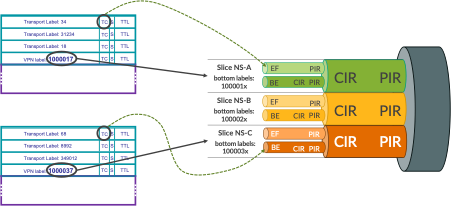
In this lab L3VPN labels, which will be present at the bottom of the label stack (SR-TE or TI-LFA could use multiple transport labels above bottom service label) in the packet, will be used for slice identification, as depicted in Figure 4.
Following L3VPN label ranges are used in this lab (again, this is just simple example – Junos link slicing framework doesn’t put any restrictions here):
Slice name |
min label |
max label |
|---|---|---|
NS-A |
1000010 |
1000019 |
NS-B |
1000020 |
1000029 |
NS-C |
1000030 |
1000039 |
The selected label ranges are from the default Junos range used for static labels, as outlined in CLI-Output 3, lines 11 and 17.
STEP-7 (PE21/PE11 router)
 1	kszarkowicz@PE21> show mpls label usage
 2	Label space Total   Available        Applications
 3	LSI         949984  949983 (100.00%) BGP/LDP VPLS with no-tunnel-services, BGP L3VPN with vrf-table-label
 4	Block       949984  949983 (100.00%) BGP/LDP VPLS with tunnel-services, BGP L2VPN
 5	Dynamic     949984  949983 (100.00%) RSVP, LDP, PW, L3VPN, RSVP-P2MP, LDP-P2MP, MVPN, EVPN, BGP
 6	Static      48576   48567  (99.98% ) Static LSP, Static PW
 7	Effective Ranges
 8	Range name  Shared with Start   End
 9	Dynamic     16      99999
 10	Dynamic     150000  999999
 11	Static      1000000 1048575
 12	SRGB        100000  149999   ISIS
 13	Configured Ranges
 14	Range name  Shared with Start   End
 15	Dynamic     16      99999
 16	Dynamic     150000  999999
 17	Static      1000000 1048575
 18	SRGB        100000  149999   ISIS
If for a particular deployment different MPLS label ranges should be used for slice identification (e.g., in multi-vendor environment, when 3rd party equipment cannot use range 1000000-1048575 for static label), the static label range could be changed with ‘set protocols mpls label-range’ command. This lab uses default static label range.
Now, when the VRFs are orchestrated on PE routers, they must be orchestrated with appropriate VRF labels (Configuration 5).
STEP-8 (PE21/PE11 router)
Configuration |
|---|
set routing-instances RI-VRF17 vrf-table-label static 1000017 |
set routing-instances RI-VRF27 vrf-table-label static 1000027 |
set routing-instances RI-VRF37 vrf-table-label static 1000037 |
 1	routing-instances {
 2	    RI-VRF17 {
 3	        vrf-table-label static 1000017;
 4	    }
 5	    RI-VRF27 {
 6	        vrf-table-label static 1000027;
 7	    }
 8	    RI-VRF37 {
 9	        vrf-table-label static 1000037;
 10	    }
 11	}
With this configuration, traffic of VRF17 will use service (bottom) label 1000017, traffic of VRF27 will use service (bottom) label 1000027, and traffic of VRF37 will use service (bottom) label 1000037. This corresponds to the MPLS label ranges defined in Table 3.
When the packets arrive to P1, which do not have any VRF, but should perform slicing on inter-AS links, packets can be classified to slices based on the bottom label ranges (Configuration 6).
STEP-9 (P1/P2 Router)
Configuration |
|---|
set interfaces ge-0/0/1 unit 0 family mpls filter input FF-MPLS-SLICE-CLASSIFIER |
set firewall family mpls filter FF-MPLS-SLICE-CLASSIFIER term TR-SLICE-A from label 1000010-1000019 bottom |
set firewall family mpls filter FF-MPLS-SLICE-CLASSIFIER term TR-SLICE-A then slice NS-A |
set firewall family mpls filter FF-MPLS-SLICE-CLASSIFIER term TR-SLICE-A then count CT-SLICE-A |
set firewall family mpls filter FF-MPLS-SLICE-CLASSIFIER term TR-SLICE-A then accept |
set firewall family mpls filter FF-MPLS-SLICE-CLASSIFIER term TR-SLICE-B from label 1000020-1000029 bottom |
set firewall family mpls filter FF-MPLS-SLICE-CLASSIFIER term TR-SLICE-B then slice NS-B |
set firewall family mpls filter FF-MPLS-SLICE-CLASSIFIER term TR-SLICE-B then count CT-SLICE-B |
set firewall family mpls filter FF-MPLS-SLICE-CLASSIFIER term TR-SLICE-B then accept |
set firewall family mpls filter FF-MPLS-SLICE-CLASSIFIER term TR-SLICE-C from label 1000030-1000039 bottom |
set firewall family mpls filter FF-MPLS-SLICE-CLASSIFIER term TR-SLICE-C then slice NS-C |
set firewall family mpls filter FF-MPLS-SLICE-CLASSIFIER term TR-SLICE-C then count CT-SLICE-C |
set firewall family mpls filter FF-MPLS-SLICE-CLASSIFIER term TR-SLICE-C then accept |
set firewall family mpls filter FF-MPLS-SLICE-CLASSIFIER term TR-ALL then count CT-NON-SLICED |
set firewall family mpls filter FF-MPLS-SLICE-CLASSIFIER term TR-ALL then accept |
 1	interfaces {
 2	    ge-0/0/1 {
 3	        unit 0 {
 4	            family mpls {
 5	                filter {
 6	                    input FF-MPLS-SLICE-CLASSIFIER;
 7	                }
 8	            }
 9	        }
 10	    }
 11	}
 12	firewall {
 13	    family mpls {
 14	        filter FF-MPLS-SLICE-CLASSIFIER {
 15	            term TR-SLICE-A {
 16	                from {
 17	                    label 1000010-1000019 {
 18	                        bottom;
 19	                    }
 20	                }
 21	                then {
 22	                    slice NS-A;
 23	                    count CT-SLICE-A;
 24	                    accept;
 25	                }
 26	            }
 27	            term TR-SLICE-B {
 28	                from {
 29	                    label 1000020-1000029 {
 30	                        bottom;
 31	                    }
 32	                }
 33	                then {
 34	                    slice NS-B;
 35	                    count CT-SLICE-B;
 36	                    accept;
 37	                }
 38	            }
 39	            term TR-SLICE-C {
 40	                from {
 41	                    label 1000030-1000039 {
 42	                        bottom;
 43	                    }
 44	                }
 45	                then {
 46	                    slice NS-C;
 47	                    count CT-SLICE-C;
 48	                    accept;
 49	                }
 50	            }
 51	            term TR-ALL {
 52	                then {
 53	                    count CT-NON-SLICED;
 54	                    accept;
 55	                }
 56	            }
 57	        }
 58	    }
 59	}
It is pretty simple configuration. Firewall filter matches for bottom label ranges (lines 16-20, 28-32, 40-44), and assigns packets to appropriate slice (lines 22, 34, 46). MPLS packets not matched (bottom label not within specific range) are kept in the default slice. Subsequently, the firewall filter is used as input filter on the interface facing PE11 (lines 1-11).
Quick verification confirms that packets are now classified by the filter to slices (CLI-Output 4).
STEP-10 (P1/P2 Router)
 1	kszarkowicz@P1> show firewall filter FF-MPLS-SLICE-CLASSIFIER
 2
 3	Filter: FF-MPLS-SLICE-CLASSIFIER
 4	Counters:
 5	Name                                                      Bytes              Packets
 6	CT-NON-SLICED                                                 0                    0
 7	CT-SLICE-A                                             16235184                12824
 8	CT-SLICE-B                                             16235184                12824
 9	CT-SLICE-C                                             16235184                12824
When we now check the queue status of each slice, we see now some counters (CLI-Output 5):
STEP-11 (P1/P2 Router)
1 kszarkowicz@P1> show interfaces queue ge-0/0/0 slice NS-A
2 Slice : NS-A (Index : 1)
3 Anchor interface : ge-0/0/0 (Index : 152)
4 Forwarding classes: 16 supported, 4 in use
5 Egress queues: 8 supported, 4 in use
6 Queue: 0, Forwarding classes: FC-BE
7 Queued:
8 Packets : 15686 97 pps
9 Bytes : 20454544 1019264 bps
10 Transmitted:
11 Packets : 15686 97 pps
12 Bytes : 20454544 1019264 bps
13 Tail-dropped packets : 0 0 pps
14 RL-dropped packets : 0 0 pps
15 RL-dropped bytes : 0 0 bps
16 RED-dropped packets : 0 0 pps
17 Low : 0 0 pps
18 Medium-low : 0 0 pps
19 Medium-high : 0 0 pps
20 High : 0 0 pps
21 RED-dropped bytes : 0 0 bps
22 Low : 0 0 bps
23 Medium-low : 0 0 bps
24 Medium-high : 0 0 bps
25 High : 0 0 bps
26 Queue: 1, Forwarding classes: FC-EF
27 Queued:
28 Packets : 15686 97 pps
29 Bytes : 20454544 1019520 bps
30 Transmitted:
31 Packets : 15686 97 pps
32 Bytes : 20454544 1019520 bps
33 Tail-dropped packets : 0 0 pps
34 RL-dropped packets : 0 0 pps
35 RL-dropped bytes : 0 0 bps
36 RED-dropped packets : 0 0 pps
37 Low : 0 0 pps
38 Medium-low : 0 0 pps
39 Medium-high : 0 0 pps
40 High : 0 0 pps
41 RED-dropped bytes : 0 0 bps
42 Low : 0 0 bps
43 Medium-low : 0 0 bps
44 Medium-high : 0 0 bps
45 High : 0 0 bps
46
47 (omitted for brevity)
48
49
50
51 kszarkowicz@P1> show interfaces queue ge-0/0/0 slice NS-B
52 Slice : NS-B (Index : 2)
53 Anchor interface : ge-0/0/0 (Index : 152)
54 Forwarding classes: 16 supported, 4 in use
55 Egress queues: 8 supported, 4 in use
56 Queue: 0, Forwarding classes: FC-BE
57 Queued:
58 Packets : 17193 97 pps
59 Bytes : 22419672 1020928 bps
60 Transmitted:
61 Packets : 17193 97 pps
62 Bytes : 22419672 1020928 bps
63 Tail-dropped packets : 0 0 pps
64 RL-dropped packets : 0 0 pps
65 RL-dropped bytes : 0 0 bps
66 RED-dropped packets : 0 0 pps
67 Low : 0 0 pps
68 Medium-low : 0 0 pps
69 Medium-high : 0 0 pps
70 High : 0 0 pps
71 RED-dropped bytes : 0 0 bps
72 Low : 0 0 bps
73 Medium-low : 0 0 bps
74 Medium-high : 0 0 bps
75 High : 0 0 bps
76 Queue: 1, Forwarding classes: FC-EF
77 Queued:
78 Packets : 17193 97 pps
79 Bytes : 22419672 1018112 bps
80 Transmitted:
81 Packets : 17193 97 pps
82 Bytes : 22419672 1018112 bps
83 Tail-dropped packets : 0 0 pps
84 RL-dropped packets : 0 0 pps
85 RL-dropped bytes : 0 0 bps
86 RED-dropped packets : 0 0 pps
87 Low : 0 0 pps
88 Medium-low : 0 0 pps
89 Medium-high : 0 0 pps
90 High : 0 0 pps
91 RED-dropped bytes : 0 0 bps
92 Low : 0 0 bps
93 Medium-low : 0 0 bps
94 Medium-high : 0 0 bps
95 High : 0 0 bps
96
97 (omitted for brevity)
98
99
100
101 kszarkowicz@P1> show interfaces queue ge-0/0/0 slice NS-C
102 Slice : NS-C (Index : 3)
103 Anchor interface : ge-0/0/0 (Index : 152)
104 Forwarding classes: 16 supported, 4 in use
105 Egress queues: 8 supported, 4 in use
106 Queue: 0, Forwarding classes: FC-BE
107 Queued:
108 Packets : 17618 97 pps
109 Bytes : 22973872 1017472 bps
110 Transmitted:
111 Packets : 17618 97 pps
112 Bytes : 22973872 1017472 bps
113 Tail-dropped packets : 0 0 pps
114 RL-dropped packets : 0 0 pps
115 RL-dropped bytes : 0 0 bps
116 RED-dropped packets : 0 0 pps
117 Low : 0 0 pps
118 Medium-low : 0 0 pps
119 Medium-high : 0 0 pps
120 High : 0 0 pps
121 RED-dropped bytes : 0 0 bps
122 Low : 0 0 bps
123 Medium-low : 0 0 bps
124 Medium-high : 0 0 bps
125 High : 0 0 bps
126 Queue: 1, Forwarding classes: FC-EF
127 Queued:
128 Packets : 17618 97 pps
129 Bytes : 22973872 1020288 bps
130 Transmitted:
131 Packets : 17618 97 pps
132 Bytes : 22973872 1020288 bps
133 Tail-dropped packets : 0 0 pps
134 RL-dropped packets : 0 0 pps
135 RL-dropped bytes : 0 0 bps
136 RED-dropped packets : 0 0 pps
137 Low : 0 0 pps
138 Medium-low : 0 0 pps
139 Medium-high : 0 0 pps
140 High : 0 0 pps
141 RED-dropped bytes : 0 0 bps
142 Low : 0 0 bps
143 Medium-low : 0 0 bps
144 Medium-high : 0 0 bps
145 High : 0 0 bps
146
147 (omitted for brevity)
We see around 2 Mbps of traffic in each slice, with 1 Mbps in each forwarding class in each slice (remaining two forwarding classes in each slice are not used in this example, therefore not shown for brevity). All traffic is passing through without any drops, as there is no congestion on the link (so, guaranteed rate doesn’t matter), and all slices are within their maximum rate limits (thus, no shaping happens, neither).
This looks good.
Now, let’s add some more traffic to the picture.
Assigning traffic to slices – SRv6
This time, let’s add SRv6 traffic. And yes, the same link slice can carry different traffic types. We can mix both MPLS and SRv6 flows within the same slice, and apply common QoS guarantees and constraints for such mixed slice. The Junos link slicing framework is very flexible.
The process of assigning traffic to slices is similar to MPLS at the high-level. However, this time we don’t have MPLS labels, but SRv6 SIDs. So, we need to identify the slices based on SRv6 SID. SRv6 SID is a 128-bit long data structure, divided into Locator:Function:Argument fields. The division is flexible, and each field can be further decomposed to carry various information.
One example of the of SRv6 SID allocation scheme, used in this lab, is presented in Figure 5.
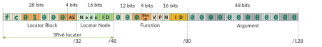
4 bits in the SRv6 locator are used for AS (Domain ID), 16 bits are kept for Node ID. Function as well has designated bits for slice ID (4 bits) and VPN ID (16 bits). Please remember, it is just an example. Depending on the actual use case and requirements, Locator:Function space can be arranged in different ways. For example, slice ID could be part of the SRv6 Locator, not part of Function.
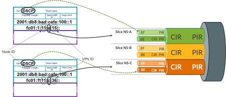
Figure 6 shows the slice selection based on slice ID encoded in SRv6 SID.
Base configuration (already pre-configured) for SRv6 Locator and End SID on PE21 is outlined in Configuration 7.
 1	routing-options {
 2	    source-packet-routing {
 3	        srv6 {
 4	            locator SL-000 {
 5	                fc01:2:21::/48;
 6	                block-length 32;
 7	                function-length 32;
 8	                static-function-max-entries 1048575;
 9	            }
 10	            no-reduced-srh;
 11	        }
 12	    }
 13	}
 14	protocols {
 15	    isis {
 16	        source-packet-routing {
 17	            srv6 {
 18	                locator SL-000 {
 19	                    end-sid fc01:2:21:0:1234:: {
 20	                        flavor {
 21	                            psp;
 22	                            usp;
 23	                            usd;
 24	                        }
 25	                    }
 26	                }
 27	            }
 28	        }
 29	    }
 30	}
Now, the interesting part is the SRv6 End.DT46 SID allocation scheme. Currently configured SRv6 End.DT46 SID allocation scheme is dynamic. That is, SRv6 End.DT46 SID values are dynamically allocated. However, in order to encode Slice ID in the SRv6 End.DT46 SID value, SRv6 End.DT46 SID values must be allocated manually (Configuration 8).
STEP-12 (PE21/PE11 Router)
On Router config prompt, type “load merge terminal”
Paste the Configurations present in Appendix Section which is Present towards the end of this document.After Pasting the configurations, Hit enter and then ctrl-D and commit
Note: The configuration present in Appendix section is same as the below Configuration but without line numbers.
 1	routing-instances {
 2	    RI-VRF15 {
 3	        protocols {
 4	            bgp {
 5	                source-packet-routing {
 6	                    srv6 {
 7	                        locator SL-000 {
 8	                            end-dt46-sid fc01:2:21:a:15::;
 9	                        }
 10	                    }
 11	                }
 12	            }
 13	        }
 14	    }
 15	    RI-VRF16 {
 16	        protocols {
 17	            bgp {
 18	                source-packet-routing {
 19	                    srv6 {
 20	                        locator SL-000 {
 21	                            end-dt46-sid fc01:2:21:a:16::;
 22	                        }
 23	                    }
 24	                }
 25	            }
 26	        }
 27	    }
 28	    RI-VRF25 {
 29	        protocols {
 30	            bgp {
 31	                source-packet-routing {
 32	                    srv6 {
 33	                        locator SL-000 {
 34	                            end-dt46-sid fc01:2:21:b:25::;
 35	                        }
 36	                    }
 37	                }
 38	            }
 39	        }
 40	    }
 41	    RI-VRF26 {
 42	        protocols {
 43	            bgp {
 44	                source-packet-routing {
 45	                    srv6 {
 46	                        locator SL-000 {
 47	                            end-dt46-sid fc01:2:21:b:26::;
 48	                        }
 49	                    }
 50	                }
 51	            }
 52	        }
 53	    }
 54	    RI-VRF35 {
 55	        protocols {
 56	            bgp {
 57	                source-packet-routing {
 58	                    srv6 {
 59	                        locator SL-000 {
 60	                            end-dt46-sid fc01:2:21:c:35::;
 61	                        }
 62	                    }
 63	                }
 64	            }
 65	        }
 66	    }
 67	    RI-VRF36 {
 68	        protocols {
 69	            bgp {
 70	                source-packet-routing {
 71	                    srv6 {
 72	                        locator SL-000 {
 73	                            end-dt46-sid fc01:2:21:c:36::;
 74	                        }
 75	                    }
 76	                }
 77	            }
 78	        }
 79	    }
 80	}
There are six VPNs defined, two for each slice – note ‘a’, ‘b’ and ‘c’ in the SID Function part (lines 8, 21, 34, 47, 60, 73), which is the agreed slice ID. Behind slice ID, you can see VPN ID (note VPN IDs: 15, 16, 25, 26, 35, 36).
Now, when the packets are sent with SRv6 encapsulation (essentially IP in IPv6 encapsulation), the destination address of the outer IPv6 header is equal to the SRv6 End.DT46 SID. Therefore, on P1 router, we need to match for specific bits encoding slice ID in the destination address of the packet, to classify the packet to a particular slice. For this, it is helpful to understand the IPv6 header structure (Figure 7).
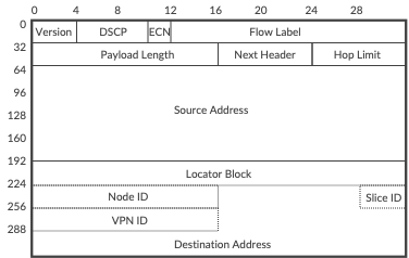
Initial fields from IPv6 header occupy 64 bits, source address is 128 bits, which gives 192 bits. When looking at the Figure 5, we can observe that SRv6 Locator occupies additional 48 bits (32 bits locator block +16 bits node ID), and most left byte (8 bits) from function is not used. This gives us in total 192 + 48 + 8 = 248 bits, or 31 bytes. Therefore, in order to match for slice ID, we will need to match 32nd byte in the IPv6 header.
To match the slice ID on P1 router we will use firewall filter with flexible match condition. This filter provides great flexibility, practically allowing to match any particular bits in the packet header (Configuration 9).
STEP-13 (P1/P2 Router)
Configuration |
|---|
set interfaces ge-0/0/1 unit 0 family inet6 filter input FF-SRV6-SLICE-CLASSIFIER |
set firewall family inet6 filter FF-SRV6-SLICE-CLASSIFIER term TR-SLICE-A from flexible-match-mask mask-in-hex 0xf |
set firewall family inet6 filter FF-SRV6-SLICE-CLASSIFIER term TR-SLICE-A from flexible-match-mask prefix 0xa |
set firewall family inet6 filter FF-SRV6-SLICE-CLASSIFIER term TR-SLICE-A from flexible-match-mask flexible-mask-name FM-SLICE-ID |
set firewall family inet6 filter FF-SRV6-SLICE-CLASSIFIER term TR-SLICE-A then slice NS-A |
set firewall family inet6 filter FF-SRV6-SLICE-CLASSIFIER term TR-SLICE-A then count CT-SLICE-A |
set firewall family inet6 filter FF-SRV6-SLICE-CLASSIFIER term TR-SLICE-A then accept |
set firewall family inet6 filter FF-SRV6-SLICE-CLASSIFIER term TR-SLICE-B from flexible-match-mask mask-in-hex 0xf |
set firewall family inet6 filter FF-SRV6-SLICE-CLASSIFIER term TR-SLICE-B from flexible-match-mask prefix 0xb |
set firewall family inet6 filter FF-SRV6-SLICE-CLASSIFIER term TR-SLICE-B from flexible-match-mask flexible-mask-name FM-SLICE-ID |
set firewall family inet6 filter FF-SRV6-SLICE-CLASSIFIER term TR-SLICE-B then slice NS-B |
set firewall family inet6 filter FF-SRV6-SLICE-CLASSIFIER term TR-SLICE-B then count CT-SLICE-B |
set firewall family inet6 filter FF-SRV6-SLICE-CLASSIFIER term TR-SLICE-B then accept |
set firewall family inet6 filter FF-SRV6-SLICE-CLASSIFIER term TR-SLICE-C from flexible-match-mask mask-in-hex 0xf |
set firewall family inet6 filter FF-SRV6-SLICE-CLASSIFIER term TR-SLICE-C from flexible-match-mask prefix 0xc |
set firewall family inet6 filter FF-SRV6-SLICE-CLASSIFIER term TR-SLICE-C from flexible-match-mask flexible-mask-name FM-SLICE-ID |
set firewall family inet6 filter FF-SRV6-SLICE-CLASSIFIER term TR-SLICE-C then slice NS-C |
set firewall family inet6 filter FF-SRV6-SLICE-CLASSIFIER term TR-SLICE-C then count CT-SLICE-C |
set firewall family inet6 filter FF-SRV6-SLICE-CLASSIFIER term TR-SLICE-C then accept |
set firewall family inet6 filter FF-SRV6-SLICE-CLASSIFIER term TR-ALL then count CT-NON-SLICED |
set firewall family inet6 filter FF-SRV6-SLICE-CLASSIFIER term TR-ALL then accept |
set firewall flexible-match FM-SLICE-ID match-start layer-3 |
set firewall flexible-match FM-SLICE-ID byte-off set 31 |
set firewall flexible-match FM-SLICE-ID bit-off set 0 |
set firewall flexible-match FM-SLICE-ID bit-length 8 |
 1	interfaces {
 2	    ge-0/0/1 {
 3	        unit 0 {
 4	            family inet6 {
 5	                filter {
 6	                    input FF-SRV6-SLICE-CLASSIFIER;
 7	                }
 8	            }
 9	        }
 10	    }
 11	}
 12	firewall{
 13	    family inet6 {
 14	        filter FF-SRV6-SLICE-CLASSIFIER {
 15	            term TR-SLICE-A {
 16	                from {
 17	                    flexible-match-mask {
 18	                        mask-in-hex 0xf;
 19	                        prefix 0xa;
 20	                        flexible-mask-name FM-SLICE-ID;
 21	                    }
 22	                }
 23	                then {
 24	                    slice NS-A;
 25	                    count CT-SLICE-A;
 26	                    accept;
 27	                }
 28	            }
 29	            term TR-SLICE-B {
 30	                from {
 31	                    flexible-match-mask {
 32	                        mask-in-hex 0xf;
 33	                        prefix 0xb;
 34	                        flexible-mask-name FM-SLICE-ID;
 35	                    }
 36	                }
 37	                then {
 38	                    slice NS-B;
 39	                    count CT-SLICE-B;
 40	                    accept;
 41	                }
 42	            }
 43	            term TR-SLICE-C {
 44	                from {
 45	                    flexible-match-mask {
 46	                        mask-in-hex 0xf;
 47	                        prefix 0xc;
 48	                        flexible-mask-name FM-SLICE-ID;
 49	                    }
 50	                }
 51	                then {
 52	                    slice NS-C;
 53	                    count CT-SLICE-C;
 54	                    accept;
 55	                }
 56	            }
 57	            term TR-ALL {
 58	                then {
 59	                    count CT-NON-SLICED;
 60	                    accept;
 61	                }
 62	            }
 63	        }
 64	    }
 65	    flexible-match FM-SLICE-ID {
 66	        match-start layer-3;
 67	        byte-offset 31;
 68	        bit-offset 0;
 69	        bit-length 8;
 70	    }
 71	}
Lines 65-70 define the flexible match mask, which essentially is the location in the packet, where our match should be performed. In this particular case, the match will be performed in the 32nd byte (byte offset 31, i.e., we are skipping first 31 bytes) of layer 3 header. This flexible match mask is then used in the IPv6 firewall filter so, the layer 3 header becomes IPv6 header (lines 20, 34, 48). The filter has further mask to narrow down the match to last 4 bits (lines 18, 32, 46) within the byte selected by flexible match mask. And, we are looking for specific values – 0xa, 0xb and 0xc – in these 4 bits (lines 19, 33, 46) to assign packets to specific slices (lines24, 38, 52). Similar to MPLS filter, this IPv6 filter is applied as input filter on the interface facing PE11 (lines 1-11).
Before performing any verification, let’s summarize current configuration state:
Slice-aware H-QoS (link slicing) configured on inter-AS link, with three slices having different min/max bandwidth constraints, each slice with two forwarding classes
9 VRFs on PE routers, 3 VRFs per slice. Within each slice, 2 VRFs use SRv6 as underlay and 1 VRF uses MPLS as underlay
Traffic generators generate traffic with traffic rate 2 Mbps per VRF with two forwarding classes (1 Mbps per forwarding class)
So, we have in total 6 Mbps per slice (3 Mbps per forwarding class in each slice)
Each slice on inter-AS link has mixed SRv6 and MPLS traffic
Now, let’s check the statistics for both MPLS and SRv6 based slice classification (CLI-Output 6).
STEP-14 (P1/P2 Router)
 1	kszarkowicz@P1> show firewall
 2
 3	Filter: FF-SRV6-SLICE-CLASSIFIER
 4	Counters:
 5	Name                                                      Bytes              Packets
 6	CT-NON-SLICED                                           1760584                22535
 7	CT-SLICE-A                                            175950390               135555
 8	CT-SLICE-B                                            175949092               135554
 9	CT-SLICE-C                                            175949092               135554
 10
 11	Filter: FF-MPLS-SLICE-CLASSIFIER
 12	Counters:
 13	Name                                                      Bytes              Packets
 14	CT-NON-SLICED                                                 0                    0
 15	CT-SLICE-A                                           3189241368              2519148
 16	CT-SLICE-B                                           3189240102              2519147
 17	CT-SLICE-C                                           3189240102              2519147
We can observe that both MPLS and IPv6 (SRv6) traffic is assigned to the slices. For IPv6 traffic we have small amount not assigned to any particular slice – this is control traffic (e.g., BGP), which is not matched explicitly in the firewall filter. In the real-life deployment, it is recommended to assign control traffic to a separate ‘control plane’ slice, with some guarantees (1-5% of link capacity) to avoid suppression of control plane traffic by other slices.
Now, checking the slice queue statistics we can make interesting observations (CLI-Output 7).
STEP-15 (P1/P2 Router)
1 kszarkowicz@P1> show interfaces queue ge-0/0/0 slice NS-A
2 Slice : NS-A (Index : 1)
3 Anchor interface : ge-0/0/0 (Index : 152)
4 Forwarding classes: 16 supported, 4 in use
5 Egress queues: 8 supported, 4 in use
6 Queue: 0, Forwarding classes: FC-BE
7 Queued:
8 Packets : 2685763 293 pps
9 Bytes : 3533512904 3110656 bps
10 Transmitted:
11 Packets : 2685763 293 pps
12 Bytes : 3533512904 3110656 bps
13 Tail-dropped packets : 0 0 pps
14 RL-dropped packets : 0 0 pps
15 RL-dropped bytes : 0 0 bps
16 RED-dropped packets : 0 0 pps
17 Low : 0 0 pps
18 Medium-low : 0 0 pps
19 Medium-high : 0 0 pps
20 High : 0 0 pps
21 RED-dropped bytes : 0 0 bps
22 Low : 0 0 bps
23 Medium-low : 0 0 bps
24 Medium-high : 0 0 bps
25 High : 0 0 bps
26 Queue: 1, Forwarding classes: FC-EF
27 Queued:
28 Packets : 2685761 292 pps
29 Bytes : 3533510232 3101056 bps
30 Transmitted:
31 Packets : 2685761 292 pps
32 Bytes : 3533510232 3101056 bps
33 Tail-dropped packets : 0 0 pps
34 RL-dropped packets : 0 0 pps
35 RL-dropped bytes : 0 0 bps
36 RED-dropped packets : 0 0 pps
37 Low : 0 0 pps
38 Medium-low : 0 0 pps
39 Medium-high : 0 0 pps
40 High : 0 0 pps
41 RED-dropped bytes : 0 0 bps
42 Low : 0 0 bps
43 Medium-low : 0 0 bps
44 Medium-high : 0 0 bps
45 High : 0 0 bps
46 Queue: 2, Forwarding classes: assured-forwarding
47 Queued:
48 Packets : 0 0 pps
49 Bytes : 0 0 bps
50 Transmitted:
51 Packets : 0 0 pps
52 Bytes : 0 0 bps
53 Tail-dropped packets : 0 0 pps
54 RL-dropped packets : 0 0 pps
55 RL-dropped bytes : 0 0 bps
56 RED-dropped packets : 0 0 pps
57 Low : 0 0 pps
58 Medium-low : 0 0 pps
59 Medium-high : 0 0 pps
60 High : 0 0 pps
61 RED-dropped bytes : 0 0 bps
62 Low : 0 0 bps
63 Medium-low : 0 0 bps
64 Medium-high : 0 0 bps
65 High : 0 0 bps
66
67 (omitted for brevity)
68
69
70 kszarkowicz@P1> show interfaces queue ge-0/0/0 slice NS-B
71 Slice : NS-B (Index : 2)
72 Anchor interface : ge-0/0/0 (Index : 152)
73 Forwarding classes: 16 supported, 4 in use
74 Egress queues: 8 supported, 4 in use
75 Queue: 0, Forwarding classes: FC-BE
76 Queued:
77 Packets : 2686710 292 pps
78 Bytes : 3534768528 3106816 bps
79 Transmitted:
80 Packets : 2396074 235 pps
81 Bytes : 3155297008 2502272 bps
82 Tail-dropped packets : 290636 57 pps
83 RL-dropped packets : 0 0 pps
84 RL-dropped bytes : 0 0 bps
85 RED-dropped packets : 0 0 pps
86 Low : 0 0 pps
87 Medium-low : 0 0 pps
88 Medium-high : 0 0 pps
89 High : 0 0 pps
90 RED-dropped bytes : 0 0 bps
91 Low : 0 0 bps
92 Medium-low : 0 0 bps
93 Medium-high : 0 0 bps
94 High : 0 0 bps
95 Queue: 1, Forwarding classes: FC-EF
96 Queued:
97 Packets : 2686710 292 pps
98 Bytes : 3534768528 3107712 bps
99 Transmitted:
100 Packets : 2684008 292 pps
101 Bytes : 3531240224 3104640 bps
102 Tail-dropped packets : 0 0 pps
103 RL-dropped packets : 0 0 pps
104 RL-dropped bytes : 0 0 bps
105 RED-dropped packets : 0 0 pps
106 Low : 0 0 pps
107 Medium-low : 0 0 pps
108 Medium-high : 0 0 pps
109 High : 0 0 pps
110 RED-dropped bytes : 0 0 bps
111 Low : 0 0 bps
112 Medium-low : 0 0 bps
113 Medium-high : 0 0 bps
114 High : 0 0 bps
115
116 (omitted for brevity)
117
118
119 kszarkowicz@P1> show interfaces queue ge-0/0/0 slice NS-C
120 Slice : NS-C (Index : 3)
121 Anchor interface : ge-0/0/0 (Index : 152)
122 Forwarding classes: 16 supported, 4 in use
123 Egress queues: 8 supported, 4 in use
124 Queue: 0, Forwarding classes: FC-BE
125 Queued:
126 Packets : 2690769 292 pps
127 Bytes : 3540148056 3106176 bps
128 Transmitted:
129 Packets : 2160508 187 pps
130 Bytes : 2846105824 2004608 bps
131 Tail-dropped packets : 530261 105 pps
132 RL-dropped packets : 0 0 pps
133 RL-dropped bytes : 0 0 bps
134 RED-dropped packets : 0 0 pps
135 Low : 0 0 pps
136 Medium-low : 0 0 pps
137 Medium-high : 0 0 pps
138 High : 0 0 pps
139 RED-dropped bytes : 0 0 bps
140 Low : 0 0 bps
141 Medium-low : 0 0 bps
142 Medium-high : 0 0 bps
143 High : 0 0 bps
144 Queue: 1, Forwarding classes: FC-EF
145 Queued:
146 Packets : 2690768 293 pps
147 Bytes : 3540146752 3115648 bps
148 Transmitted:
149 Packets : 2687784 293 pps
150 Bytes : 3536251520 3112576 bps
151 Tail-dropped packets : 0 0 pps
152 RL-dropped packets : 0 0 pps
153 RL-dropped bytes : 0 0 bps
154 RED-dropped packets : 0 0 pps
155 Low : 0 0 pps
156 Medium-low : 0 0 pps
157 Medium-high : 0 0 pps
158 High : 0 0 pps
159 RED-dropped bytes : 0 0 bps
160 Low : 0 0 bps
161 Medium-low : 0 0 bps
162 Medium-high : 0 0 bps
163 High : 0 0 bps
164
165 (omitted for brevity)
There are no drops in slice NS-A. In slice NS-B we observe small drops in forwarding class FC-BE. In slice NS-C we observe even bigger drops, but again in forwarding class FC-BE only. The observations are in line with the expectations (please refer to Table 2 for slice rates). Also, for slices observing drops, only FE-BE class, with low priority, is affected. Strict-priority FC-EF class is not affected.
Slice status can be monitored as well via Open JTS
Appendix
Configuration for STEP-12 (PE21/PE11 Router). After pasting the configs, go back to STEP-12
	routing-instances {
		RI-VRF15 {
			protocols {
				bgp {
					source-packet-routing {
						srv6 {
							locator SL-000 {
								end-dt46-sid fc01:2:21:a:15::;
							}
						}
					}
				}
			}
		}
		RI-VRF16 {
			protocols {
				bgp {
					source-packet-routing {
						srv6 {
							locator SL-000 {
								end-dt46-sid fc01:2:21:a:16::;
							}
						}
					}
				}
			}
		}
		RI-VRF25 {
			protocols {
				bgp {
					source-packet-routing {
						srv6 {
							locator SL-000 {
								end-dt46-sid fc01:2:21:b:25::;
							}
						}
					}
				}
			}
		}
		RI-VRF26 {
			protocols {
				bgp {
					source-packet-routing {
						srv6 {
							locator SL-000 {
								end-dt46-sid fc01:2:21:b:26::;
							}
						}
					}
				}
			}
		}
		RI-VRF35 {
			protocols {
				bgp {
					source-packet-routing {
						srv6 {
							locator SL-000 {
								end-dt46-sid fc01:2:21:c:35::;
							}
						}
					}
				}
			}
		}
		RI-VRF36 {
			protocols {
				bgp {
					source-packet-routing {
						srv6 {
							locator SL-000 {
								end-dt46-sid fc01:2:21:c:36::;
							}
						}
					}
				}
			}
		}
	}
Glossary
AS: Autonomous System
ASBR: Autonomous System Boundary Router
BGP: Border Gateway Protocol
BW: Bandwidth
CE: Customer Edge
CIR: Committed Information Rate
CLI: Command Line Interface
DSCP: Differentiated Services Code Point
Dst: Destination
eBGP: external Border Gateway Protocol
ECN: Explicit Congestion Notification
FlexE: Flexible Ethernet
Gbps: Gigabits per second
H-QoS: Hierarchical Quality of Services
iBGP: internal Border Gateway Protocol
ID: Identifier
IGP: Interior Gateway Protocol
Inter-AS: Inter Autonomous System
IP: Internet Protocol
IPv4: Internet Protocol version 4
IPv6: Internet Protocol version 6
IS-IS: Intermediate System to Intermediate System
L2: Level 2
L3VPN: Layer 3 Virtual Private Network
Mbps: Megabits per second
MPLS: Multiprotocol Label Switching
NHS: Next Hop Self
OSPF: Open Shortest Path First
P: Provider
PE: Provider Edge
PIR: Peak Information Rate
PSP: Penultimate Segment Pop
QoS: Quality of Services
RFC: Request for Comments
RIB: Routing Information Base
RR: Route Reflector
SID: Segment Identifier
SR: Segment Routing
Src: Source
SR-MPLS: Segment Routing with Multiprotocol Label Switching
SR-TE: Segment Routing Traffic Engineering
SRv6: Segment Routing version 6
TC: Traffic Class
TI-LFA: Topology Independent Loop Free Alternates
TLV: Type Length Value
USD: Ultimate Segment Decapsulation
USP: Ultimate Segment Pop
VLAN: Virtual Local Area Network
VPN: Virtual Private Network
VRF: Virtual Routing and Forwarding
You have successfully completed this Hands-On Lab!
Lab Survey
Please take 2 minutes and complet the SRv6 and MPLS Core and Edge Link SlicingHands-On Lab Survey