Apstra 6.0 Lab
Overview
The demonstration starts with a pre-configured Apstra setup that has rack type, template, logical device and blueprint already pre-configured. Day 1 and Day 2 Apstra configurations are also done to showcase creation of routing zone, virtual networks and connectivity templates. The purpose is to introduce Apstra 6.0 focusing on concepts that help in the deployment of a DC fabric with inter and intra-virtual network connectivity established and finally, understand how to identify anomalies and other features on Apstra 6.0 UI.
Day 0 activity
Discover the vEX devices using Offbox agent and manage them
Assign system IDs to respective device parameters
Day 1 activity
Verify the configuration of templates, rack types, logical devices, interface mapping, blueprint. virtual networks, routing zones, connectivity templates and routing policy
Deploy the configuration onto the fabric
Connect the leafs to an external router
Day 2 activity
Verify intra-virtual network connectivity between the hosts via tagged interfaces
Insert configuration deviation, swap links, add a configlet, create an IBA probe, create and observe root cause identification, rollback using time voyager
Starting Lab
Topology
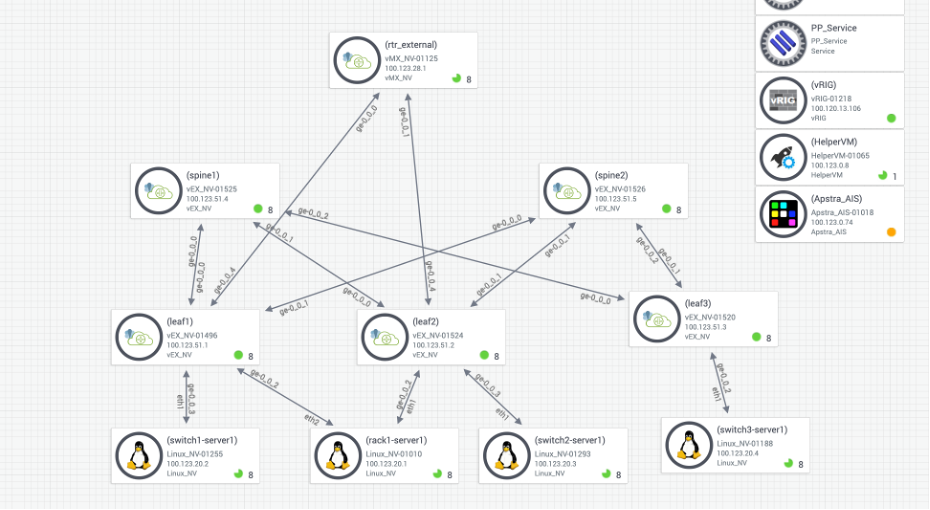
Topology consists of a 2-stage leaf spine architecture with external gateway being a vMX router. We have 4 different hosts connecting to three leafs with one of them having LAG enabled. All of them have tagged interfaces connecting to the leafs. Leaf1 and Leaf2 are connecting to the external router. Each of the leafs have a host device connected to them.
Access Details
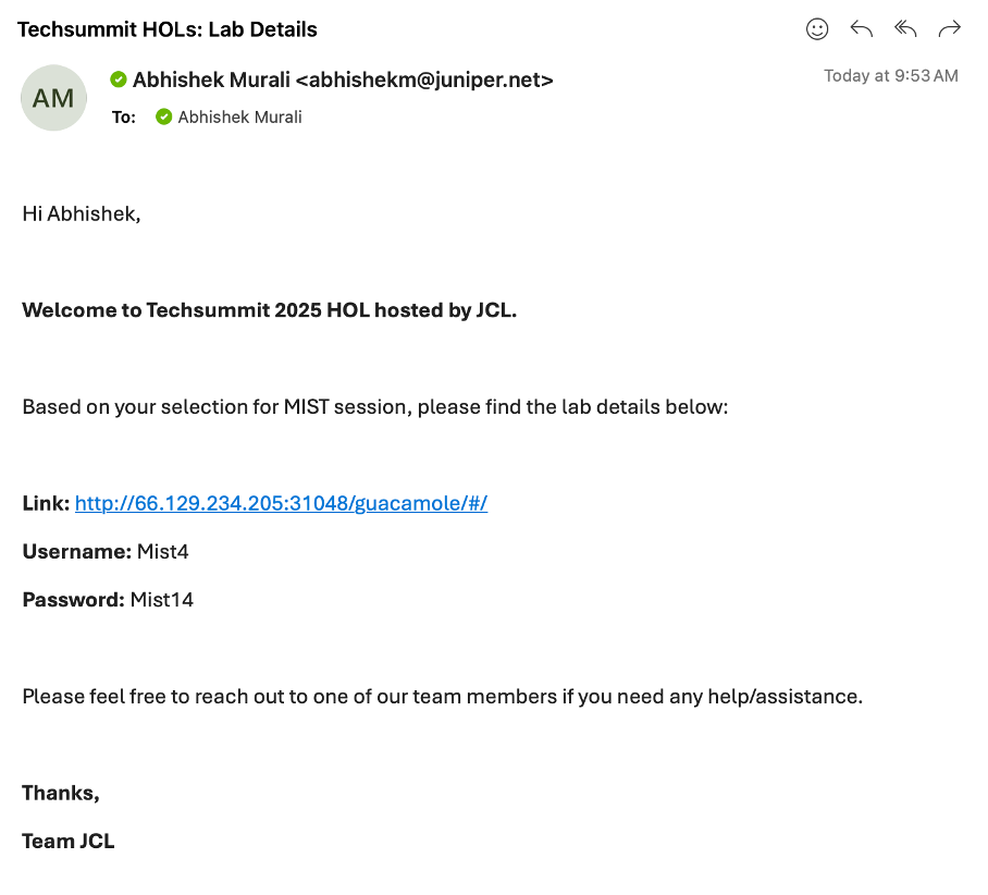
[Once you have submitted the form check your inbox and you should have received an email from (_jcl-hol@juniper.net) containing the lab details as show below.
 ]: #
]: #
Open a browser and http into server Link provided to you in the above email.
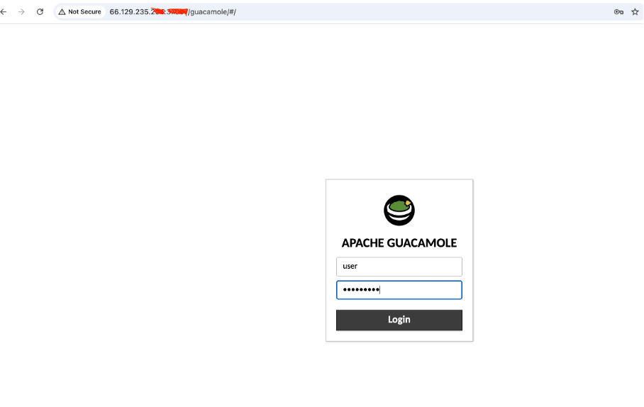
Login with username and the password shared via email.
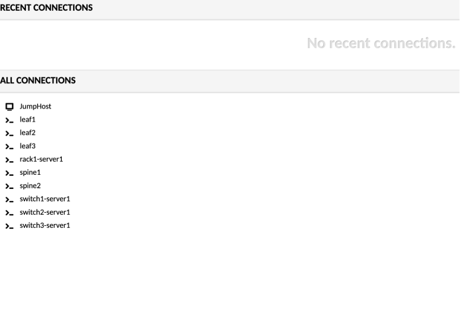
Click on JumpHost, and login using the following credentials:
user - jumpstation
password - Juniper!1

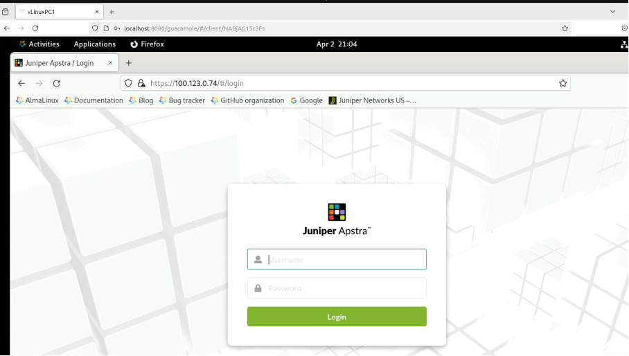
Open a Firefox browser and navigate to Apstra UI: https://100.123.0.74 with username: admin and password: Juniper!1
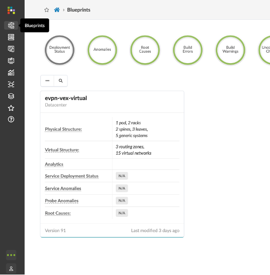
Navigate to Blueprints, You will be working with evpn-vex-virtual blueprint.
Reviewing DC Configuration (Pre-Configured)
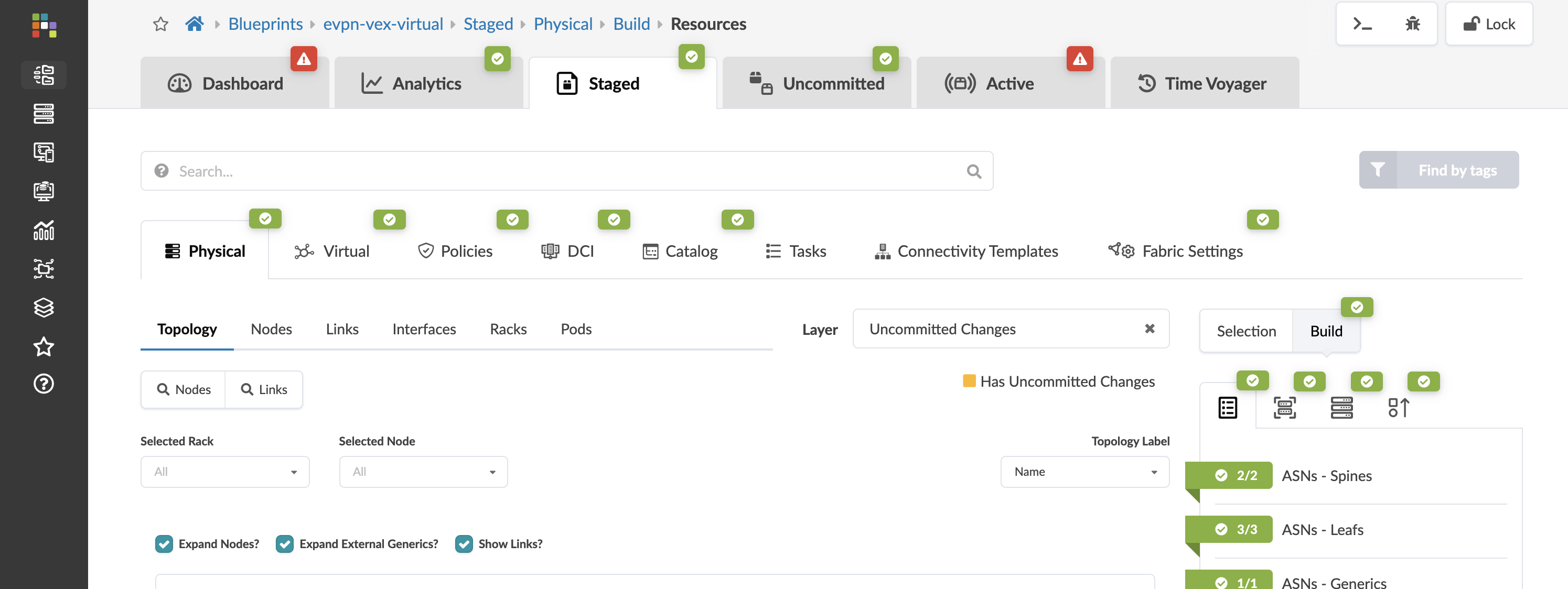
Review Resources
Navigate to Resources > IP Pools section in Apstra UI.
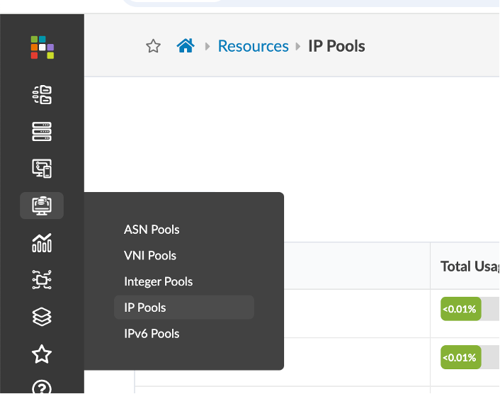
You can see that the demo is currently using three such IP Pools for the purpose of fabric and loopback connectivity.
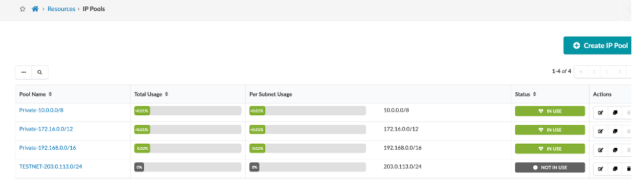
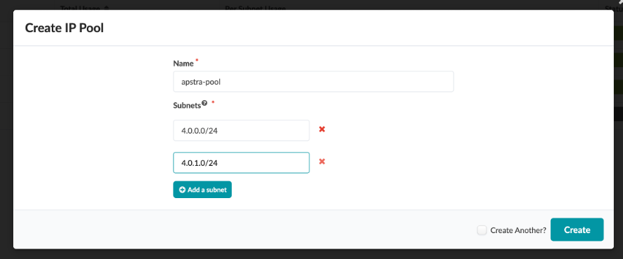
You can create multiple IP Pools using the Create IP Pool button as shown.
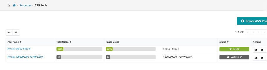
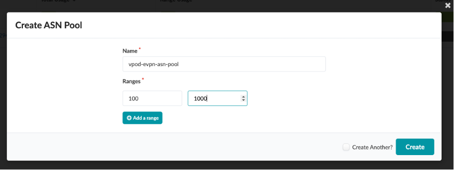
Similarly, cross check ASN and VNI Pools and view how to create an ASN pool.
Review Rack Types
Rack Types are modular definitions containing top-of-rack switches, workloads, and their associated connections. There are also redundancy protocol settings and other details contained. The racks we have built will be used in the next stages of modelling our lab fabric. Like the other building blocks we will work with, there are several pre-defined examples that come with the server. You can examine them in the list to get a feel for the possibilities. They can all be easily cloned and modified to give us the exact characteristics we need to architect our fabric.
These are already pre-configured so you just need to review them and not create them.
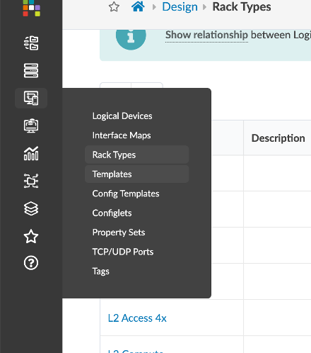
Navigate to Design > Rack Types.
We are using evpn-esi and evpn-single rack in this demo (search for them if you don’t get it immediately).
Let’s review the first rack-type, evpn-esi:
Name - evpn-esi
Fabric Connectivity Design - L3 Clos
Click on Edit
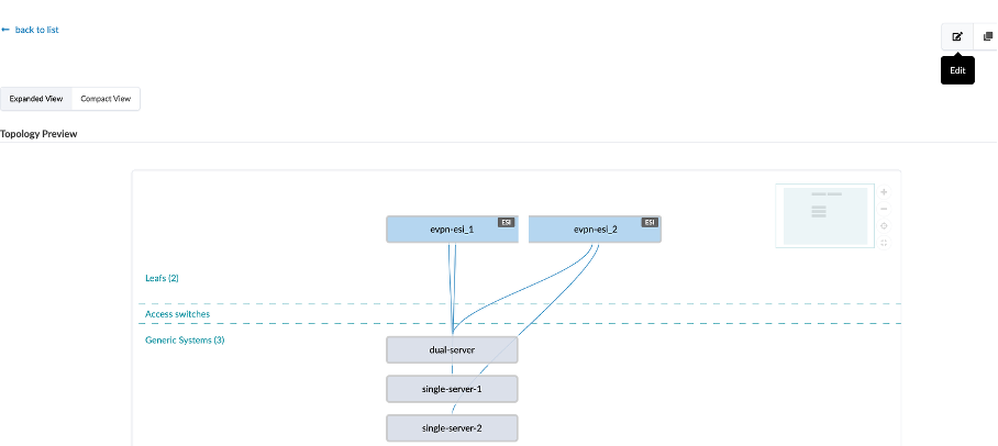
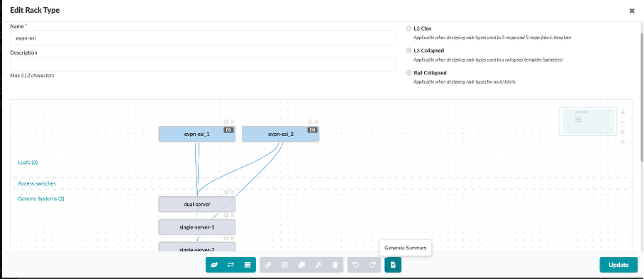
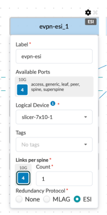
You can see that under the leafs section, we have defined the name (evpn-esi), logical device that determines the connections and role, links per spine, speed and redundancy protocol – in this case ESI.
You can view it in Generate Summary field as shown below:
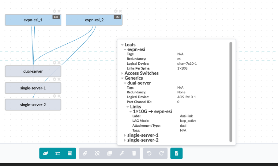
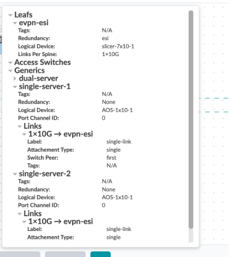
Under generic systems tab, we have defined the type of hosts and the type of connection between the hosts and the leaf devices
The dual-server is dual homed to leaf1 and leaf2 – we have defined the logical device , generic system count, the link type (dual-homed), protocol used – LACP Active and physical link count per switch with its speed.

The switch1-server and swicth2-server are single homed to leaf-1 and leaf-2 respectively.
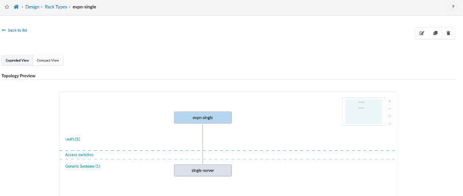
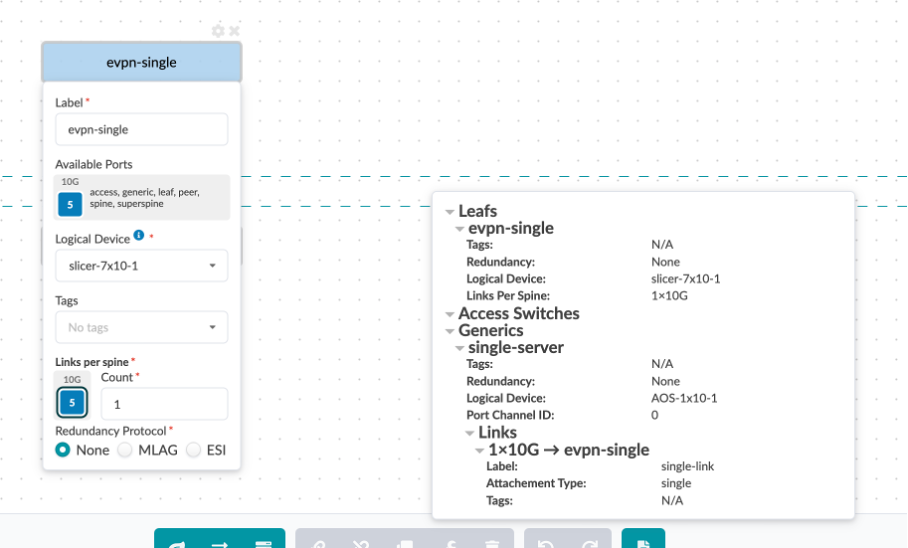
Let’s also review the second rack-type, evpn-single:
This consisting of one leaf (leaf3) and one single connection to the host device (switch3-server1) from the leaf3.
Review Templates
Templates are where we assemble the building-blocks we have constructed so far, on our journey to create a Blueprint. We have already put our devices into Racks. Now we will create a Template, where we place our Racks and other selections on how our network will operate. This is the template that we will use when it’s time to turn all our preparations into an operating fabric. (Template is already pre-created).
Navigate to Design > Templates
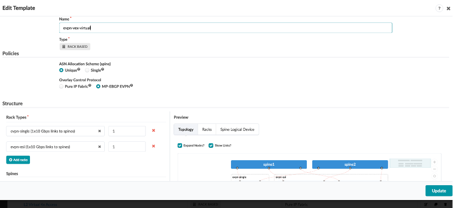
Click on evpn-vex-virtual template, and review the details:
Name - evpn-vex-virtual
Type - RACK BASED
ASN Allocation Scheme - Unique
Overlay Control Protocol - MP-EBGP EVPN
Rack Types
evpn-single
evpn-esi
Review what we have defined for the Spines:
Spine Logical Device - slicer-7x10⁻¹
Count - 2
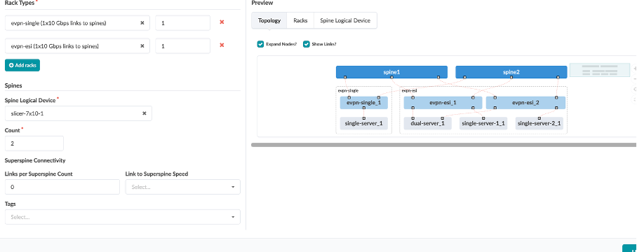
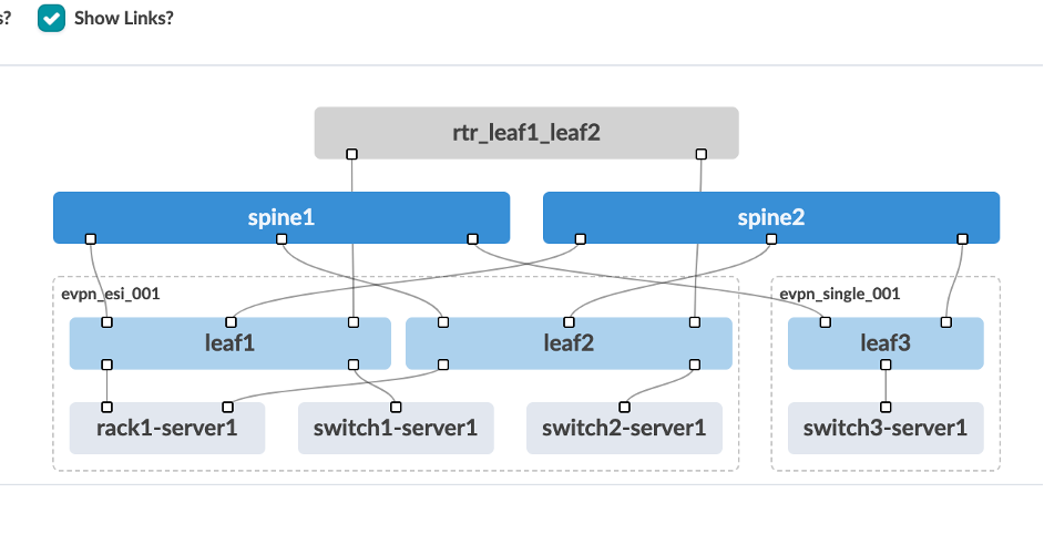
Review the logical diagram to see if it matches with the JCL topology. Now, we are ready to create the blueprint.
Deploying Blueprint
Navigate to Blueprint – evpn-vex-virtual
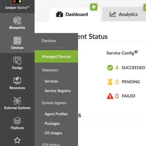
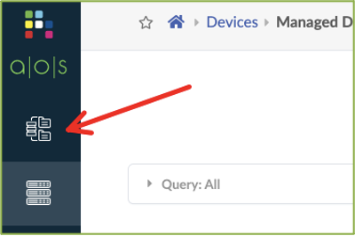
From the menu bar on the left, click the Devices icon, then click Managed Devices.
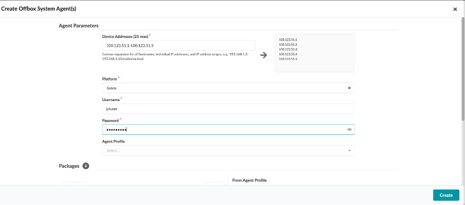
Click on Create Offbox Agent(s) at the top right of the screen,and enter the following:
Device Addresses - 100.123.51.1-100.123.51.5
Platform - Junos
Username - jcluser
Password - Juniper!1
Click on Create.
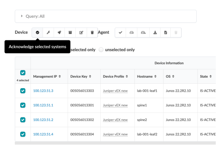
Once acknowledged, they all show up in green tick mark under “Acknowledged?” section.
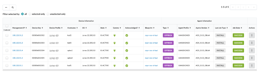
Verify all managed devices are in an Acknowledged state.
Assign System IDs to Fabric Nodes
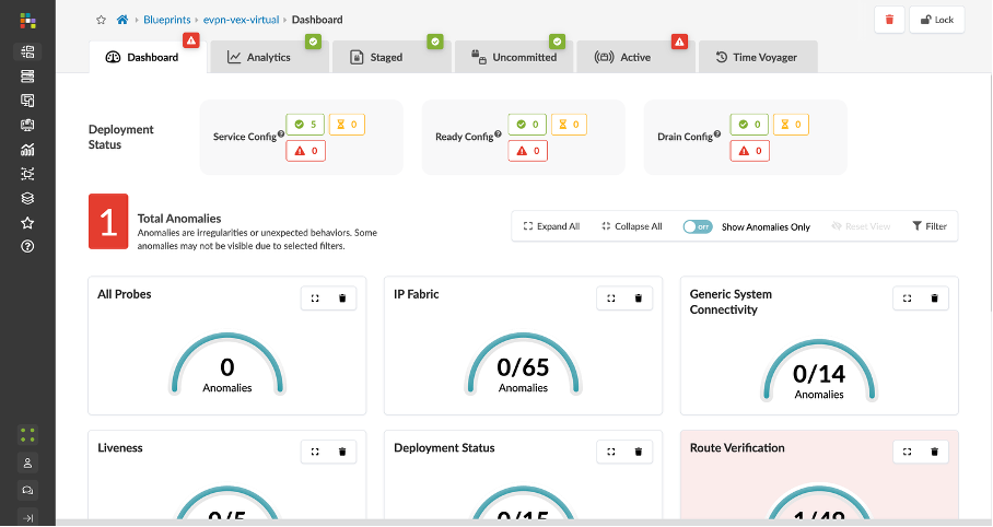
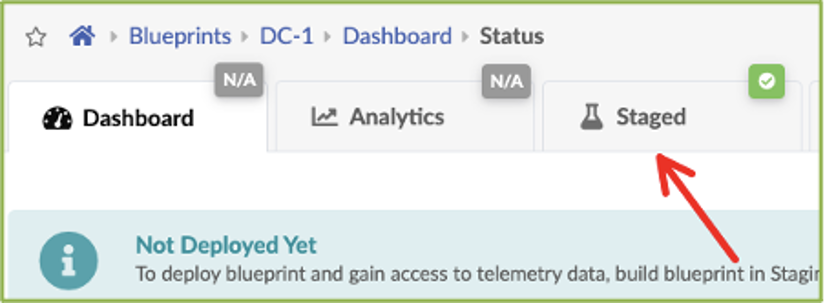
Click the Blueprints icon in the menu bar on the left and select evpn-vex-virtual blueprint.. This opens up the Blueprint Dashboard.
Navigate to the Staged tab under DC-1.
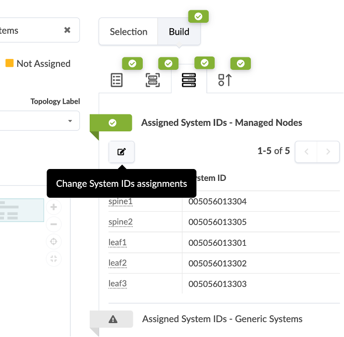
Click the Devices tab in the Build workspace on the right of the screen.
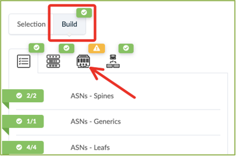
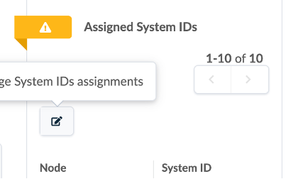
Click the yellow splat to the left of Assigned System IDs.
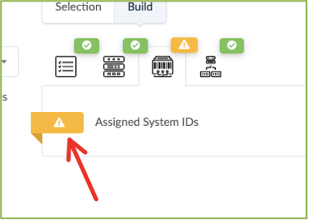
Click on Change System ID Assignment.
Associate each fabric node with the correct System ID/IP Address as shown in the img below:
Use the drop down window to assign device IDs to devices (spine, server leaf and border leaf).
Mode - Deploy (in right column)
Click on Update Assignments
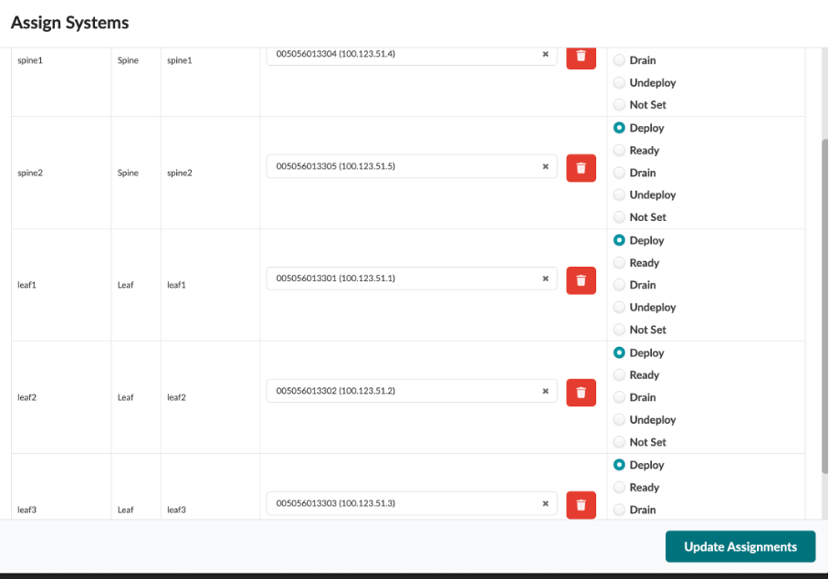
Spine1 : 100.123.51.4 Spine2 : 100.123.51.5 leaf1 : 100.123.51.1 leaf2: 100.123.51.2 leaf3: 100.123.51.3
Commit and Deploy the Blueprint
The next step is to Commit the configuration and deploy it from Apstra to the vEX devices.
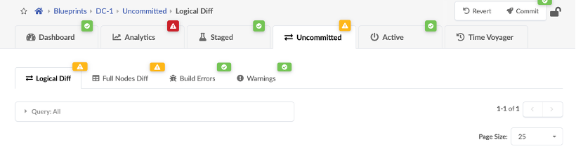
Navigate to the Uncommitted tab on the blueprint, and click Commit at the top right corner of the screen. This should take care of deploying the blueprint.
Now, wait for 3-4 mins for the deployments to finish and the alarms to resolve.

If there are no alarms, proceed, if there are alarms, reach out to the lab team.
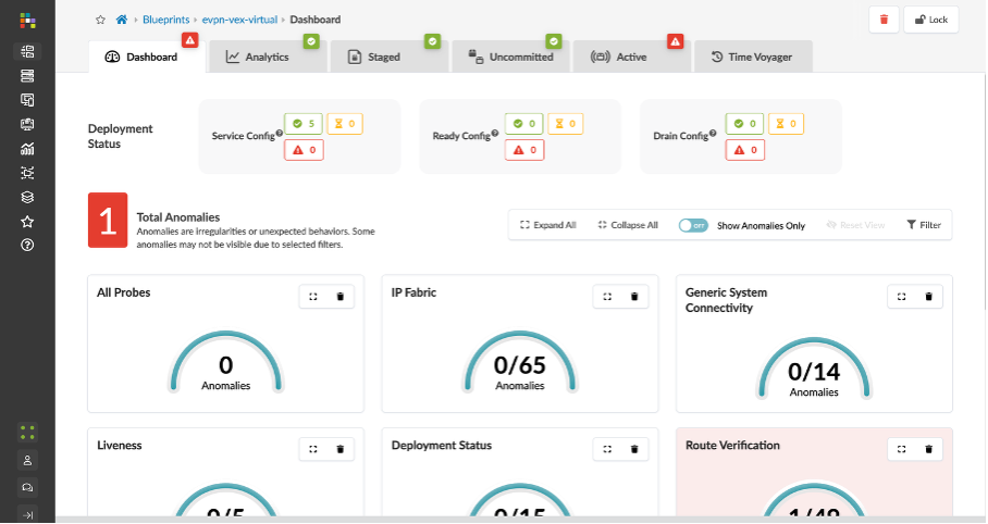
Reviewing Blueprint parameters (Pre-configured)
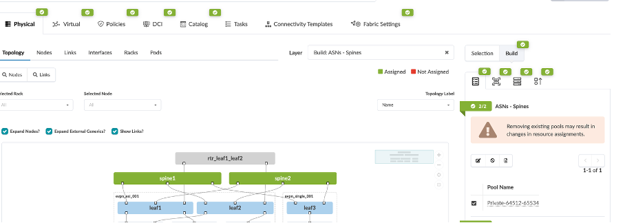
Navigate to Staged section of the Blueprint:
From the Staged – Physical – Topology, you can see the actual topology that has three leafs, two spines, four hosts connected to three different leafs and an external router connected to the leafs.
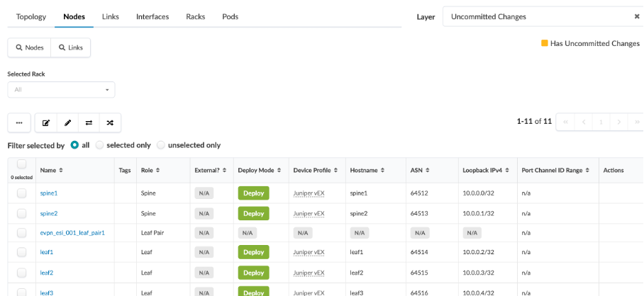
Review Nodes and Links
Navigate to Physical > Nodes, and check the information regarding each node (device) and its associated logical device, hostname, role, device profile used (in our case, Juniper vEX).
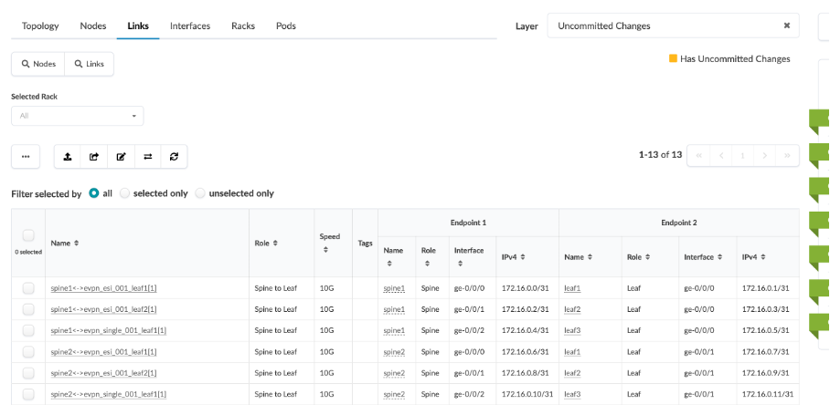
Next, click Physical > Links, and check the cabling map to see if it coincides with the JCL topology.
Review Blueprint Properties
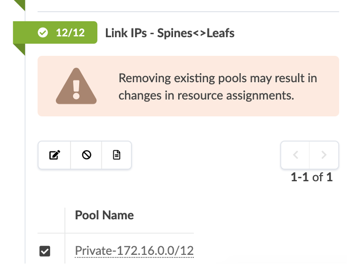
Navigate to Staged > Physical, you will see there are certain parameters of the Blueprint that we have to set are already set in this demo.
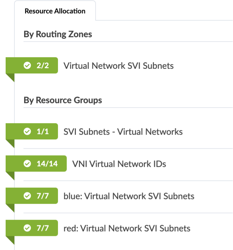
The ASN and IP pools have to be assigned to the fabric and loopback connections.
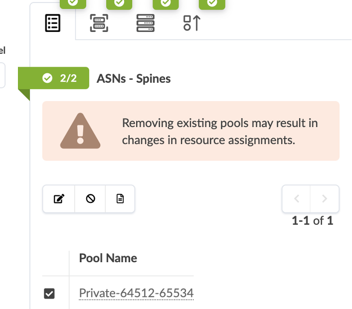
The Loopback IPs have to be to set as well.
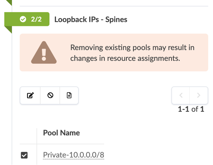
The Link IPs have to be assigned as well.
Review Routing Zones
Routing zones are created in a template where MP-EBGP EVPN is configured as the overlay control protocol. Only inter-rack virtual networks can be associated with routing zones. For a virtual network with Layer 3 SVI, the SVI will be associated with a VRF for each routing zone isolating the virtual network SVI from other tenants. This lab is for an MP-EBGP EVPN datacenter, so we’ll be using VXLAN.
Navigate to Physical > Virtual > Routing Zones, you will see there are three routing zones (also known as VRFs) created for our use-cases (Red / Blue / Default).
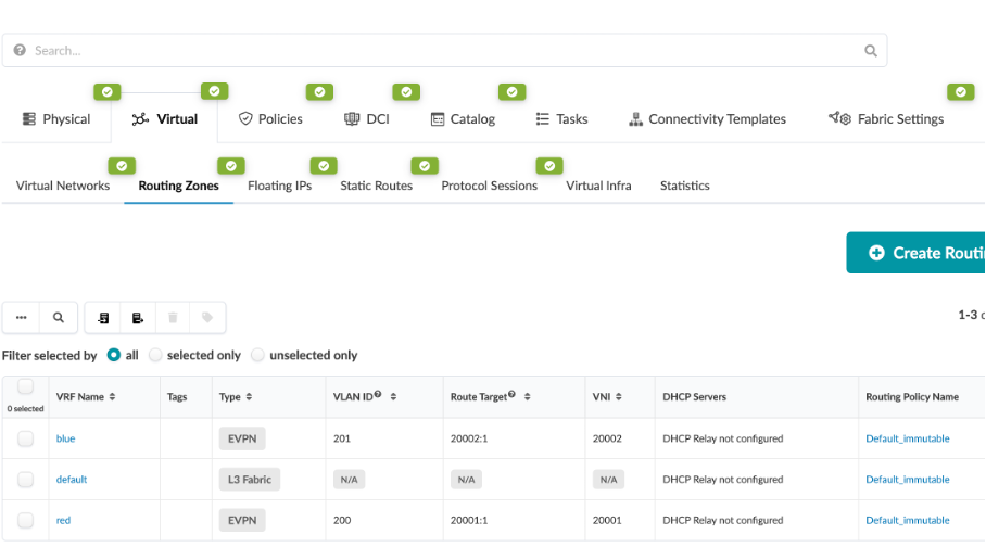
Click on the Blue routing zone, you can see that it has a VLAN ID and VNI associated with it. This is used for EVPN VXLAN connectivity across the fabric. It also has a default routing policy associated with it Similarly, for red and default routing zone.
Review Virtual Networks
Virtual networks (VN) are collections of L2 forwarding domains. In an Apstra-managed fabric, a virtual network can be constructed using either VLANs or VXLANs.
Routing zones are created in a template where MP-EBGP EVPN is configured as the overlay control protocol. Only inter-rack virtual networks can be associated with routing zones. For a virtual network with Layer 3 SVI, the SVI will be associated with a VRF for each routing zone isolating the virtual network SVI from other tenants. This lab is for an MP-EBGP EVPN datacenter, so we’ll be using VXLAN.
Navigate to Staged > Virtual > Virtual Networks, We have configured a number of different virtual networks with their respective VLAN IDs and ipv4 subnets.
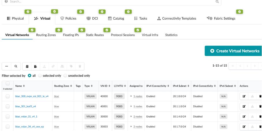
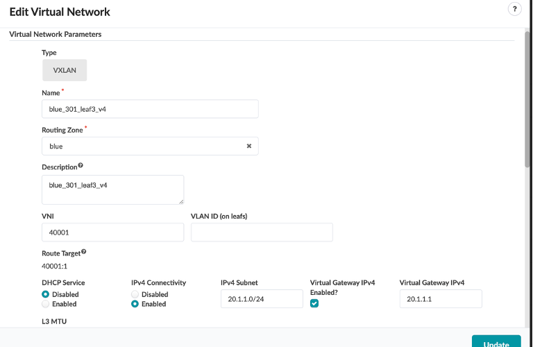
Click on one of them
You will see that it is associated withthe following:
Type - VXLAN
Name - The Virtual Network you selected
Routing Zone - blue
VNI - VNI from the VNI pool
IPv4 Subnet - IP Associated with the Virtual Network you selected
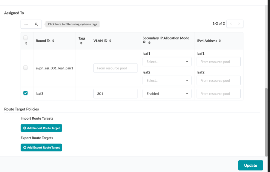
Each of these virtual networks is associated with a connectivity template defining the interface associated with the virtual network.
Review Virtual Network and Routing Zone parameters
Navigate to Virtual > Routing Zones.
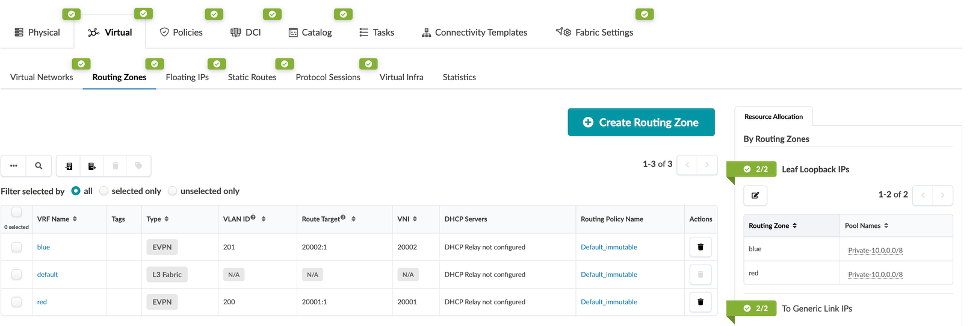
Here we can define routing zone parameters.
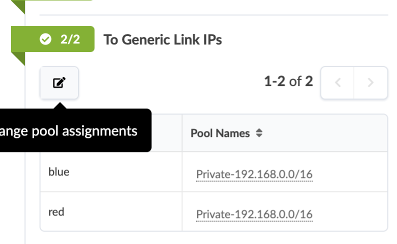
Here we can define Leaf Loopback IPs
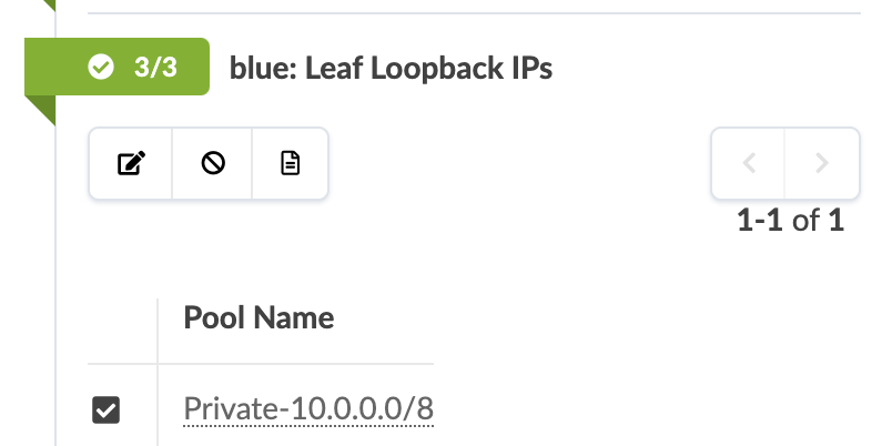
Here we can define Link IPs
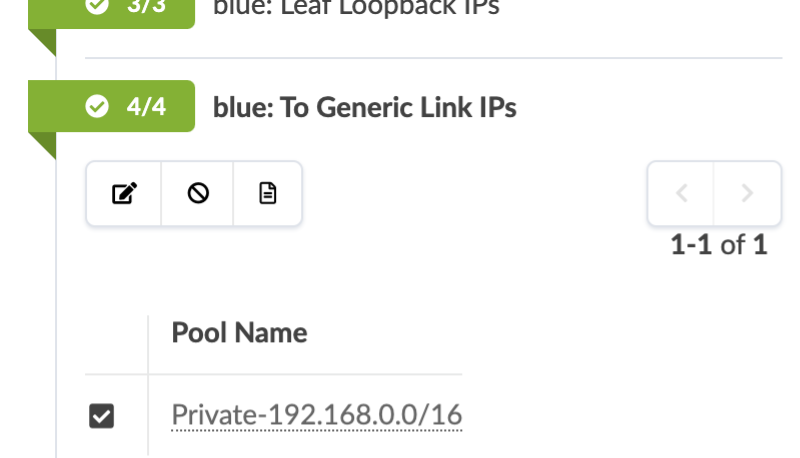
Here we can define EVPN L3 VNIs
Review Connectivity Templates
We have given the system details about how we wish to physically connect the leaf pair to the external router. Now we need to tell Apstra what kind of layer 3 characteristics need to be applied to the links. This information is placed into an object known as a Connectivity Template (CT). A CT contains the architectural details necessary for creating an IP Link with BGP peering between the leaf pair and the external router as well as hosts to leaf connectivity.
Navigate to Staged > Connectivity Templates
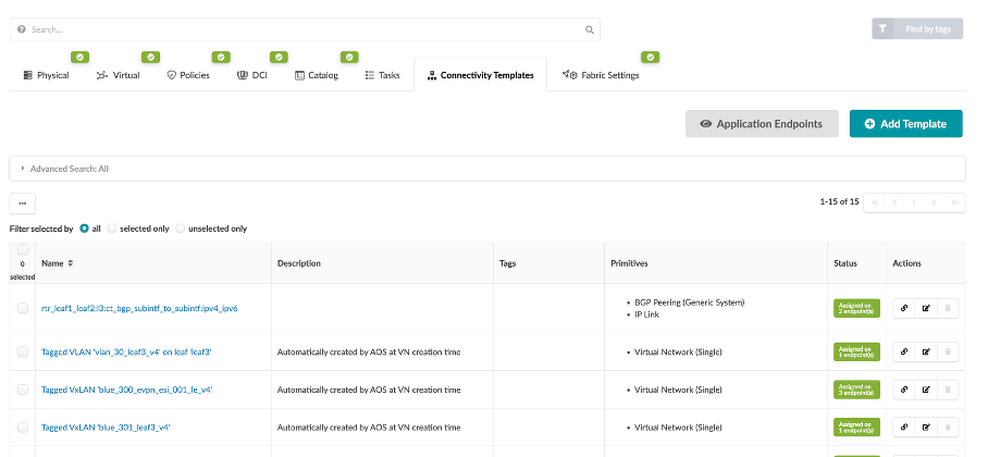
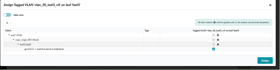
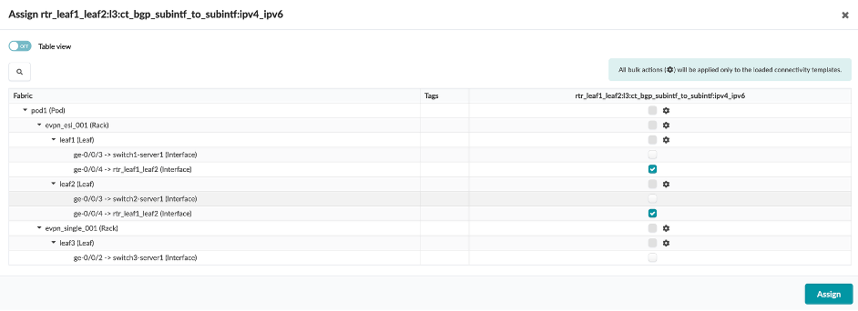
Click the Assign button (chain button) in the Actions column

You will see that the connectivity template is assigned to a particular interface based on which tagged virtual network needs to be assigned to which interface in the topology.
Click on Edit in the Actions for the rtr_leaf1 connectivity template (which connects external router to leaf1 and leaf2).

You can see that the template is created by assigning multiple endpoints (BGP and IP link properties) to it.
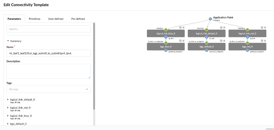
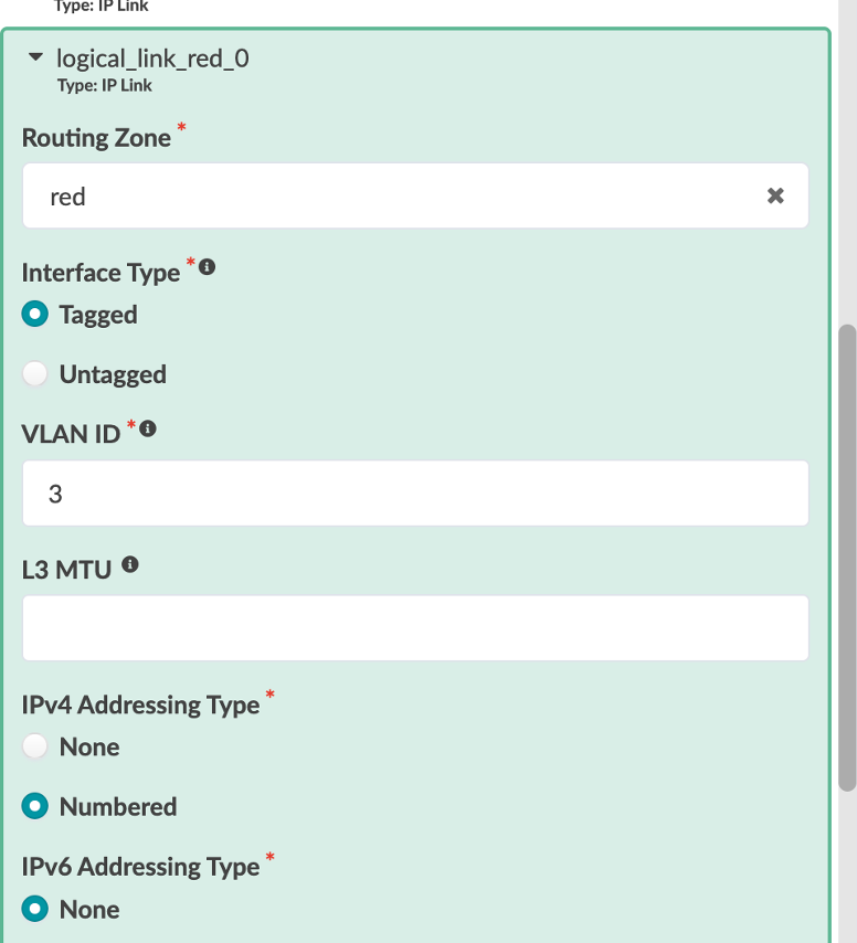
Let’s review logical_link_red_0 8Type: IP Link8
Routing Zone - Red
Interface Type - Tagged
VLAN ID - 3
IPv4 Addressing Type - Numbered
IPv6 Addressing Type - None
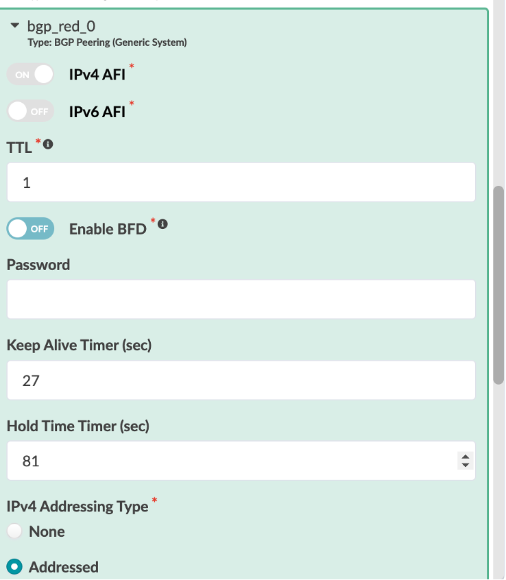
Let’s review bgp_red_0 8Type: BGP Peering (Generic System)*
IPv4 AFI - On
IPv6 AFI - Off
TTL - 1
Enable BFD - Off
IPv4 Addressing Type - Addressed
IPv6 Addressing Type - None
Neighbor ASN Type - Static
Peer From - Interface
Peer To - Interface/IP Endpoint

We have then assigned the interface connecting to the external router from Leaf1 and Leaf2 via the connectivity template.
Usecases
Usecase 1: Verify Connectivity
From Jumphost VM, open Terminal*
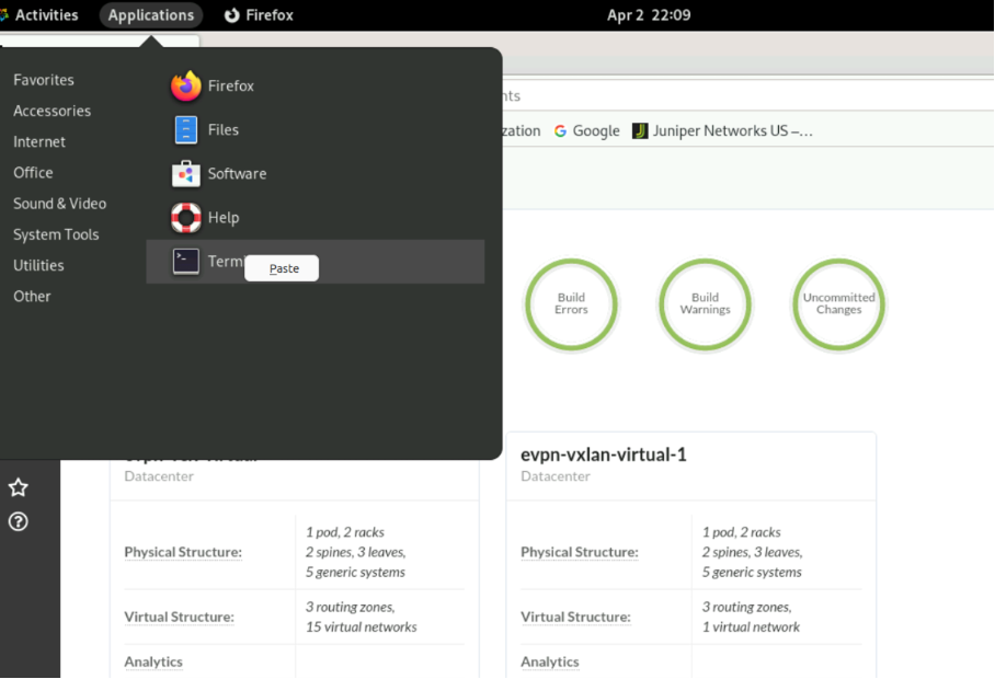
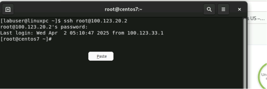
SSH into host-1 by running the following command in the terminal:
ssh root@100.123.20.2
Type the password as Juniper!1
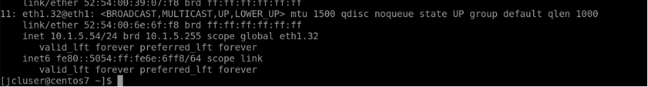
SSH into switch1-server1 connected to Leaf1. We can see that it has a tagged interface connecting to leaf1 with the IP “10.1.5.51/24”
Type “ip a” to check eth1.32 IP which is 10.1.5.51/24

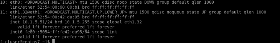
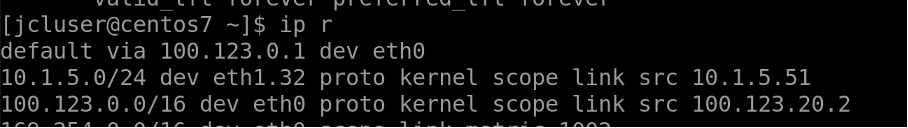
It also has a route defined for 10.1.5.0/24 network
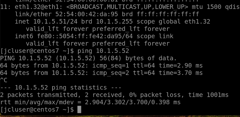
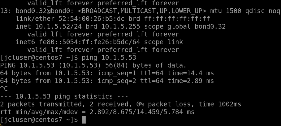
SSH into rack1-server1 (100.123.20.1) connected to Leaf1 and Leaf2. Rack1-server1 has a bond0 (LAG) interface defined with VLAN 32 and IP set to “10.1.5.52/24”, is dual homed to leaf1 and leaf2.
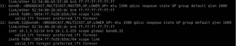

Eth1 and Eth2 belong to bond0 interface, IP - 10.1.5.53/24
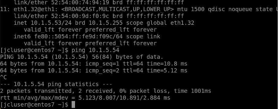
Switch2-server1 connected to Leaf2
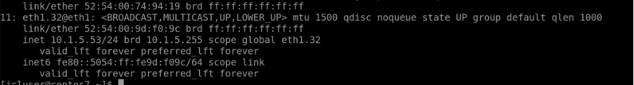
Switch3-server1 connected to Leaf3, IP - 10.1.5.54/24
In summary, Let’s try to ping between the hosts to verify intra-virtual network and routing zone connectivity across different leafs.
Switch1-server1 : 10.1.5.51/24
Rack1-server1: 10.1.5.52/24
Switch2-server1: 10.1.5.53/24
Switch3-server1: 10.1.5.54/24
Usecase 1a: Ping from Host1 to Host2
Ping 10.1.5.52 from Host1 (switch1-server1)
Usecase 1b: Ping from Host2 to Host3
Similarly, ping from Host2 (rack1-server1) to Host 3 (switch2-server1)
Usecase 1c: Ping from Host3 to Host4
Similarly, ping from host3 (switch2-server1) to Host4 (switch3-server1)
Usecase 2: Configure via Configlet
Configure an NTP server via a configlet.
Configlets are small configuration segments that are used to apply device settings that fall outside the Apstra Reference Design parameters. Examples of common Configlet usage are items like syslog, SNMP, TACACS/RADIUS, management interface ACLs, control plane policing and NTP settings. The NTP example is the one we will use to show you the process of working with Configlets.
In addition, we are going to use another mechanism called Property Sets. These increase flexibility by allowing us to use variables in a Configlet. This is quite handy if we would like to use a common Configlet structure for our devices, but not all devices require the same values. This exercise calls for us to add the Junos style and variables to an existing NTP Configlet. Property Sets will supply the IP address for the server and identify the VRF to apply the configurations into.
Always remember that Configlets are a powerful way to apply configuration that falls outside of the Apstra Reference Designs. In other words, do not use Configlets for features that Apstra manages, itself. Doing so can interfere with the proper operation of the solution. It is critical that the configurations applied in Configlets are thoroughly verified before applying them in a Blueprint. Otherwise, malformed Configlets will cause errors and interfere with deployment.
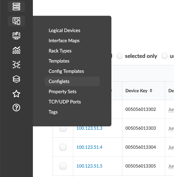
Navigate to Design > Configlets.
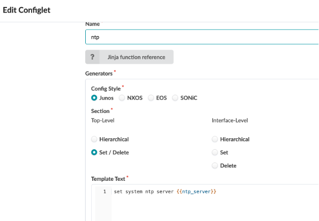
Create a Configlet using the following:
Name - ntp
Config Style - Junos
Section
Top-Level - Set / Delete
Interface-Level - None Selcted
Template Text - Set system ntp server {{ntp_server}}
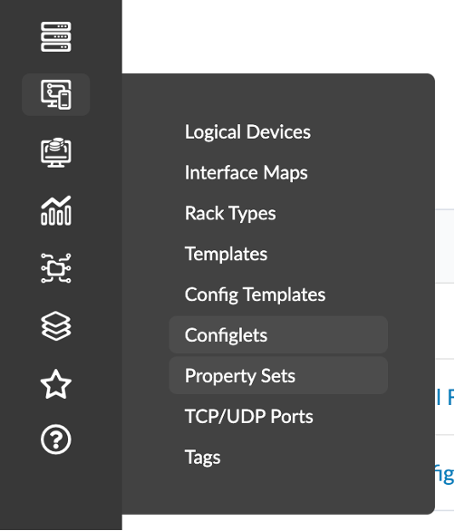
Navigate to Design > Property Set.
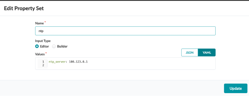
Create a Property Setusing the following:
Name - ntp
Input Type - Editor
Values - ntp_server: 100.123.0.1
Navigate to Blueprint > Staged > Catalog > Configlet.
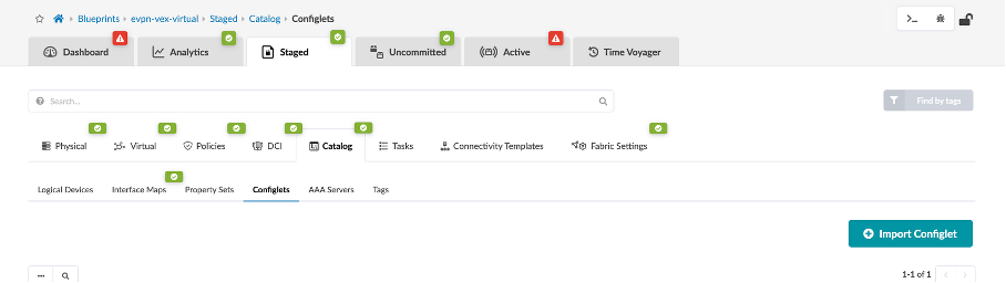
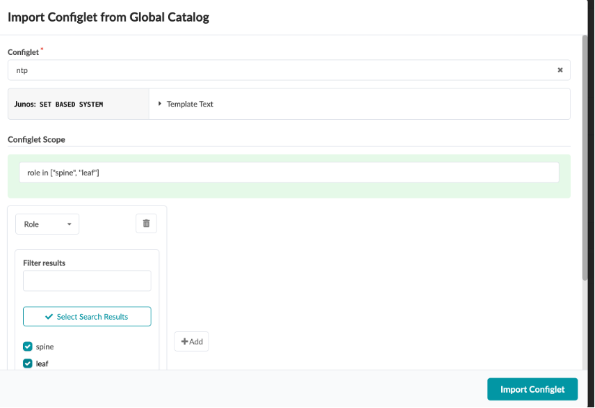
Click Import Configlet
Select ntp Server and select spine and leaf undwer roles.
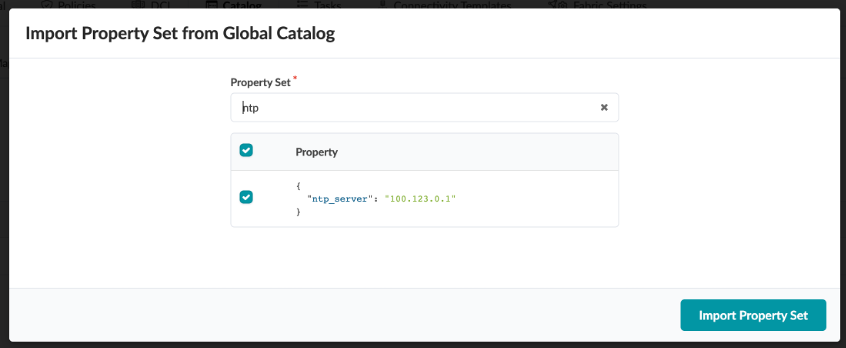
Navigate to Staged > Catalog > Property Set
Click Import Property Set
Select ntp, and click Import Property Set
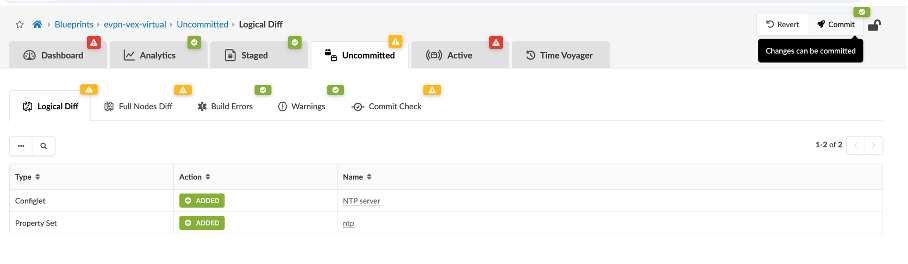
Now, click Commit and wait for successful deployment on all 5 devices.
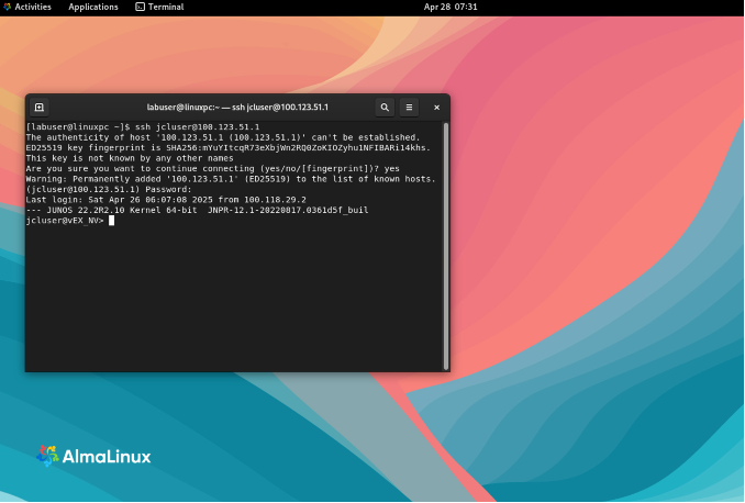
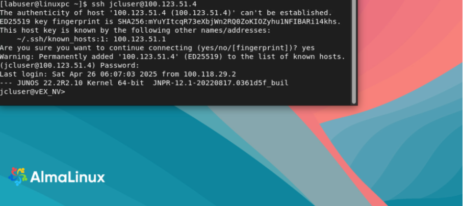
SSH into Leaf1 from Jumphost by opening Terminal and running the following:
ssh jcluser@100.123.51.1
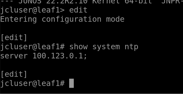
Now run the following command to verify the NTP server IP:
show system ntp
Usecase 3: Instantiate Pre-Defined IBA Probe
Navigate to Blueprint > Analytics > Probes
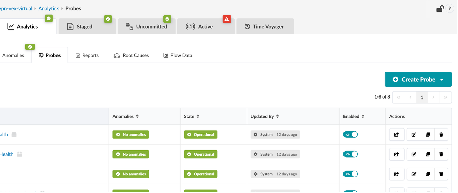
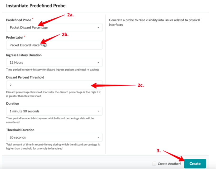
Click Create Probe, then Instantiate Predefined Probe
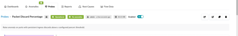
Change the Discard Percentage Threshold to 2.
Click Create
The Operational tab and No Anomalies tab should be green.
Usecase 4: Starting and Stopping Probes
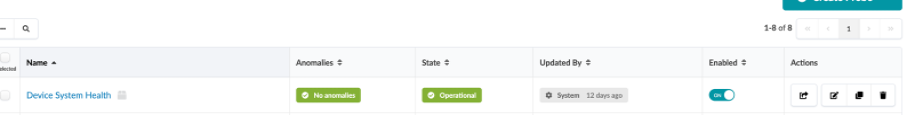
Click the Probes tab to return to the list view.
To stop an enabled probe, click the Enabled toggle off.
To start a disabled probe, click the Enabled toggle on.
Usecase 5: Root Cause Analysis
The root cause identification system automatically correlates anomalies to identify the actual cause of connectivity problems. This eliminates unnecessary work and troubleshooting for an operator.
With Root Cause Identification enabled, link or interface failures will be identified with precision. RCI can be tested in this lab pod by misconfiguring fabric links.
Navigate to Analytics > Root Causes
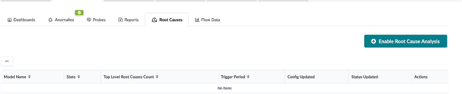
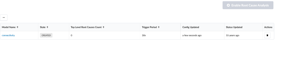
Click Enable root cause analysis
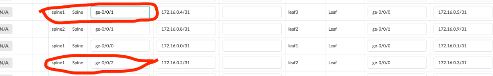
Go to Staged > Physical > Links, and click Edit cabling Map.
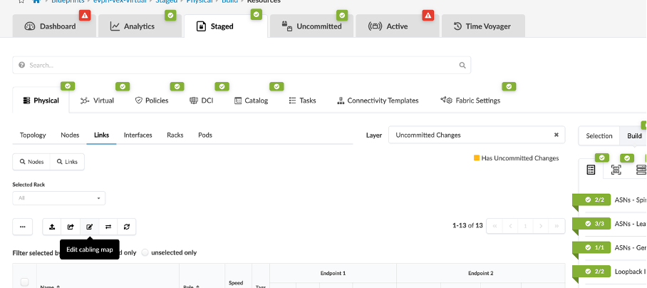
Change the following:
spine1 - ge-0/0/1 (Leaf3)
spine1 - ge-0/0/2 (Leaf2)
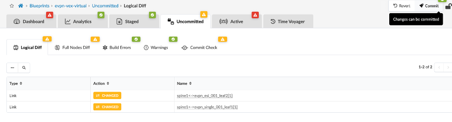
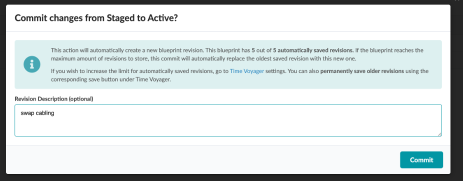
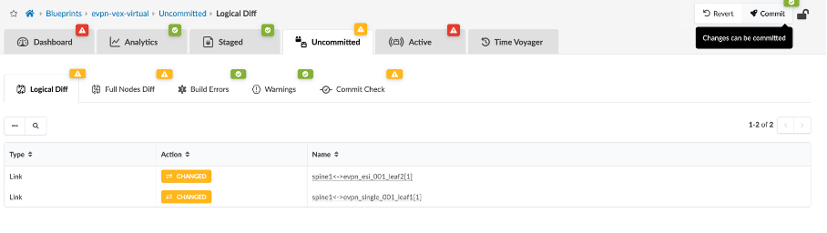
Go to Uncommitted tab, and click Commit to save the changes.
Name the commit as swap cabling.
Now go to Analytics > Root Causes.
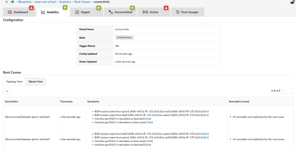
Explore all the areas of this view to see the details of the Root Cause diagnosis.
Usecase 6: Time Voyager
To go back to the previous configuration before swapping the cabling of spine-1, we can either re-edit the cabling map to point to original or use the LLDP feature or use Time voyager to roll back to the previous commit.
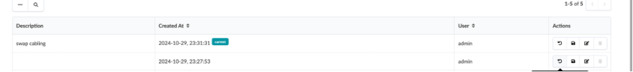
Let’s use Time Voyager to roll back to previous commit, the commit before “swap cabling” which is current.
Navigate to Time Voyager, The current configuration is “swap cabling”.
Select the one prior to that, and click on Jump to this revision icon in the Actions column.
Click on Rollback and review the information in the uncommitted tab
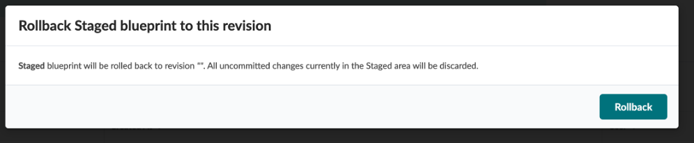
Click Commit
Cross check that the cabling map is back to its original state.

Usecase 7: Config Deviation
SSH into spine-1 from Jumphost by opening Terminal and running the following:
ssh jcluser@100.123.51.4
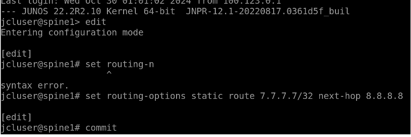
Set the routing-options by using the following commands:
edit
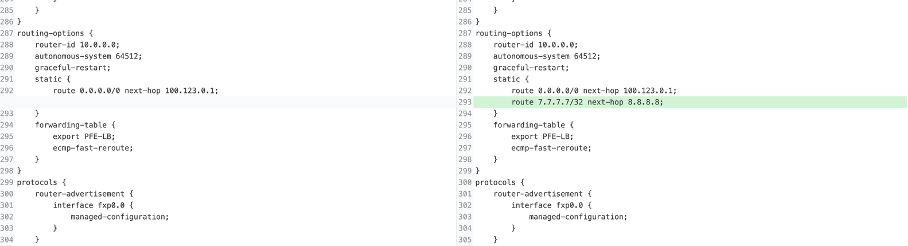
set routing-options static route 7.7.7.7/32 next-hop 8.8.8.8
commit
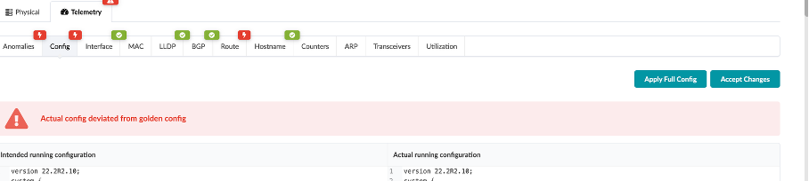
Navigate to Apstra UI, you will the Deployment Status shows a config dev error.
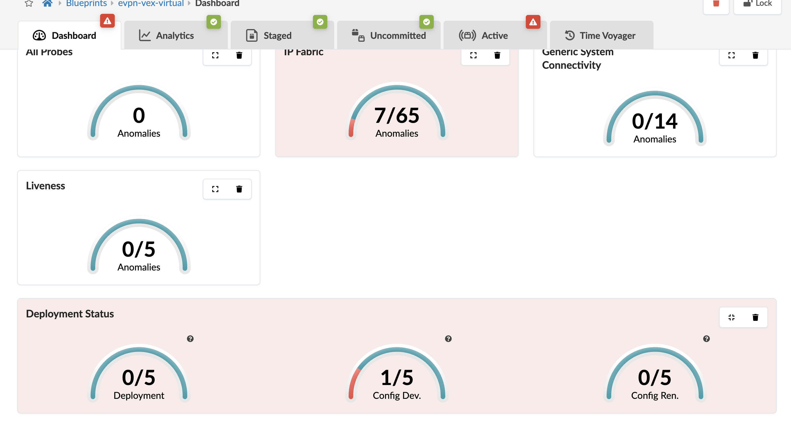
Click on the config dev error, it shows that the error is associated with spine1 and it is a route based error.

Click on spine1
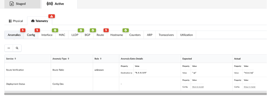
Go to the config tab.
Scroll down, and you can see where and what the inserted config is.
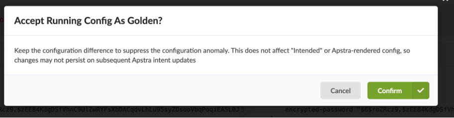
Click on Accept Changes
Click Confirm to resolve the error.
You have successfully completed this Hands-On Lab!
Try it later ?
You can find this lab and try it out on-demand in JCL at the below link:
(https://portal.cloudlabs.juniper.net/RM/Topology?b=45df00a0-7d40-4e57-9e3b-b195861e0c81&d=c78ae7c7-e93b-4708-813e-109fd780f301) this lab is available in Demonstration-US1 domain
Lab Survey
Please take 2 minutes and complet the Apstra 6.0 Hands-On Lab Survey